


G0513X/G0514X/G0514X3 Extreme Series Bandsaw
-27-
Tensioning Blade
A properly tensioned blade is essential for mak-
ing accurate cuts and is required before mak
-
ing many bandsaw adjustments. (Everytime you
replace the blade, you should perform this proce
-
dure because all blades tension differently.)
To tension the bandsaw blade:
1. Complete the Test Run procedure and make
sure the blade is tracking properly.
2. Raise the upper blade guide assembly as
high as it will go, and adjust the upper and
lower guide blocks as far away from the
blade as possible.
Note: This procedure will
NOT work if the guide blocks have any con
-
tact with the blade.
3. Engage the quick tension lever to the tight-
ened position and turn the blade tension
handwheel until the tension scale reads
between 4 and 6.
4. Turn the bandsaw ON.
5. Slowly release the tension one quarter of a
turn at a time. When you see the bandsaw
blade start to flutter, stop decreasing the ten
-
sion.
6. Now, slowly increase the tension until the
blade stops fluttering, then tighten the ten
-
sion another quarter turn.
7. Look at what the tension gauge reads and
use that as a guide for tensioning that blade
in the future.
Note: Always detension the
blade after use to increase blade life and
reduce strain on the bandsaw components.
8. Re-adjust the blade tracking as instructed on
Page 22.
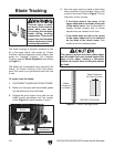
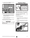
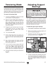
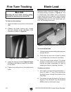
Adjusting Support
Bearings
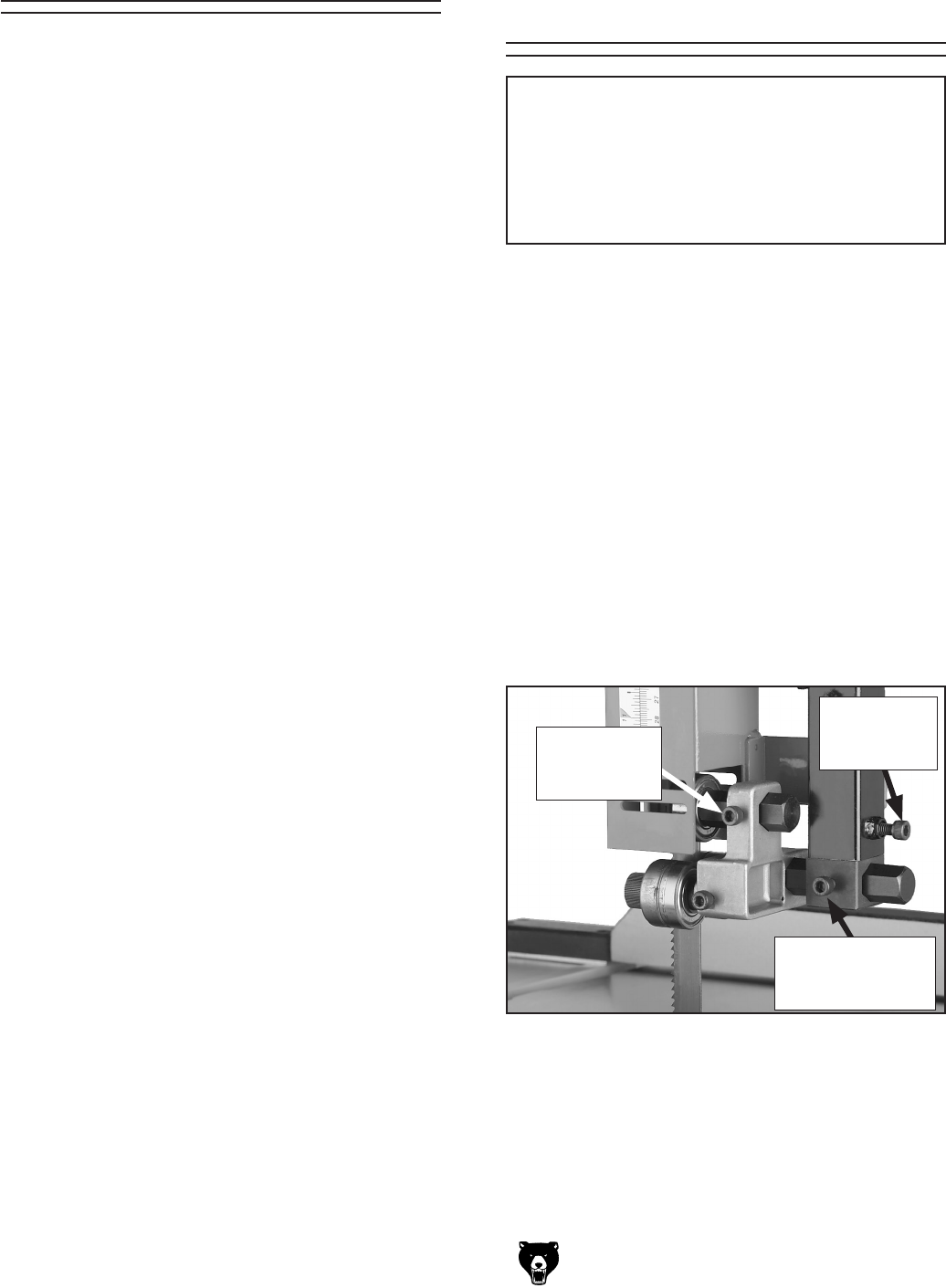
Figure 27. Upper support bearing controls.
The support bearings are positioned behind
the blade for support during cutting operations.
Proper adjustment of the support bearings is an
important part of making accurate cuts and also
keeps the blade teeth from coming in contact with
the guide bearings while cutting.
To adjust the upper support bearings:
1. DISCONNECT BANDSAW FROM POWER!
2. Make sure the blade is tracking properly and
that it is correctly tensioned.
3. Familiarize yourself with the upper support
bearing controls shown in
Figure 27.
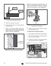
4. Loosen the guide block assembly cap screw
and rotate the blade guide assembly side-to-
side, until the blade is perpendicular with the
face of the support bearing as illustrated in
Figure 28.
Support
Bearing Cap
Screw
Guide Block
Assembly
Cap Screw
NOTICE
Whenever changing a blade or adjusting ten-
sion and tracking, the upper and lower blade
support bearings and blade guide bearings
must be properly adjusted before cutting
operations.
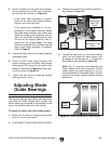
Support Bearing
Adjustment
Shaft Cap Screw