G0609 12" Parallelogram Jointer
-39-
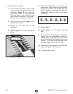
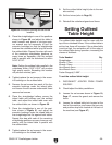
3. Place the straightedge in one of the positions
shown in
Figure 49, and adjust the table (a
small hammer and punch or pin-type span
-
ner wrench may be necessary to turn the
eccentric bushings) so that the straightedge
touches the cutterhead while lying flat across
the outfeed table. Repeat this step with each
of the remaining straightedge positions as
many times as necessary until the outfeed
table is parallel with the cutterhead to within
0.010"-0.012"
.
Note: Setting the outfeed table parallel to the
cutterhead within 0.010"-0.012" will produce
high quality results. Exceeding this number
will produce minimal gain.
4. Tighten/replace the set screws in the eccen-
tric bushings on the outfeed table.
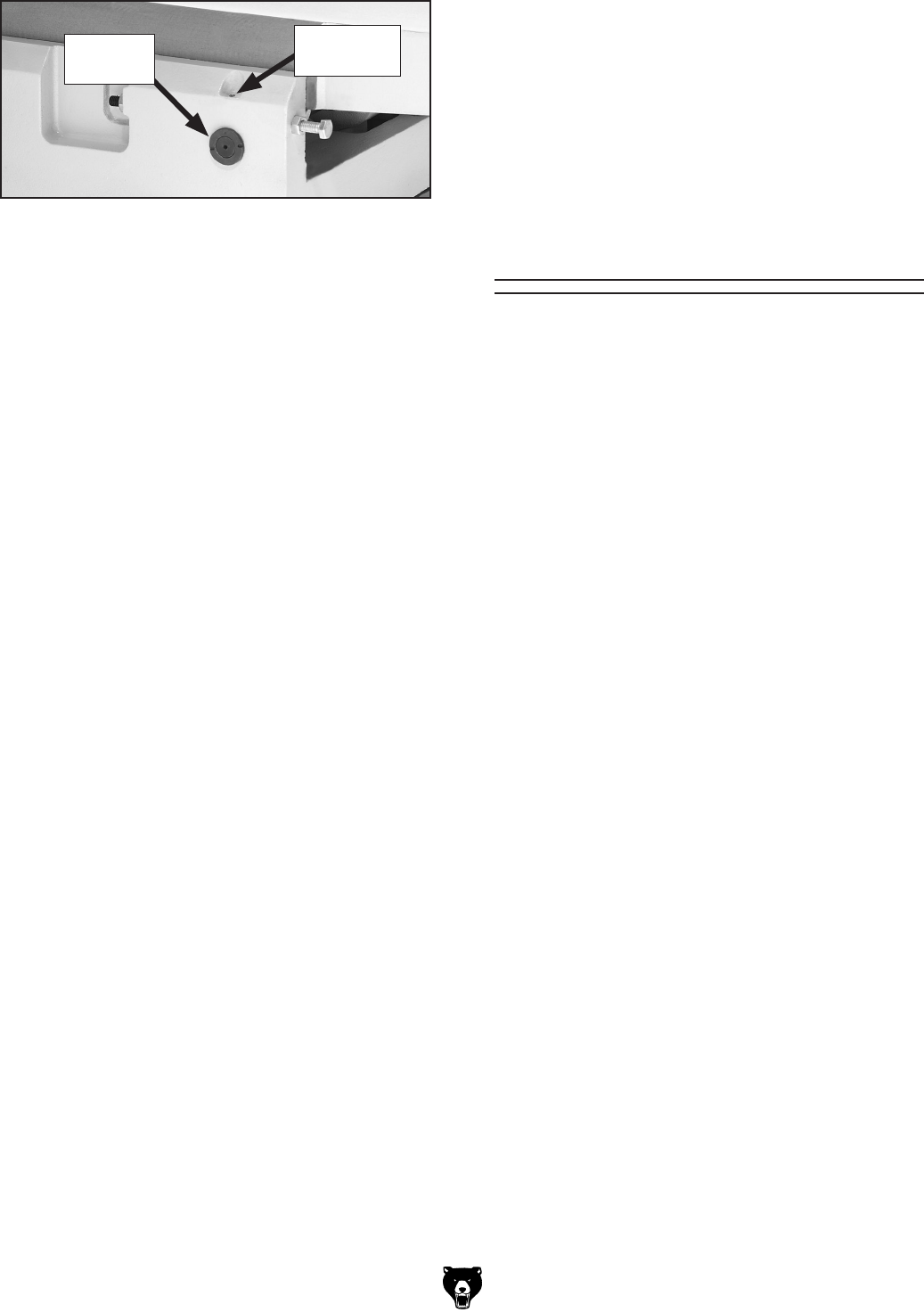
5. Remove the set screw from each of the four
eccentric bushings under the infeed table,
and loosen the set screws underneath those
removed set screws.
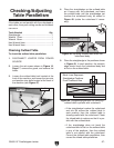
6. Place the straightedge halfway across the
infeed table and halfway over the outfeed
table, and adjust the infeed table even with
the outfeed table, as shown in
Figure 50.
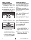
7. Place the straightedge in one of the posi-
tions shown in
Figure 51, and adjust the
eccentric bushings under the infeed table so
the straightedge lies flat against both tables.
Repeat this step with each of the remaining
straightedge positions as many times as nec
-
essary until the infeed table is parallel with
the outfeed table.
8.
Tighten/replace the set screws in the eccen-
tric bushings on the infeed table.
Setting Outfeed
Table Height
The outfeed table height must be even with the
top of the cutterhead knives. If the outfeed table is
set too low, there will be snipe. If the outfeed table
is set too high, the workpiece will hit the edge of
the outfeed table during operation, increasing the
chance of kickback.
Tools Needed Qty
Straightedge ...................................................... 1
Wrench 17mm ...................................................
1
Wrench 19mm ...................................................
1
Hex Wrench 5mm ..............................................
1
Hex Wrench 3mm ..............................................
1
Feeler Gauge(s) 0.062" .....................................
1
To set the outfeed table height:
1. DISCONNECT JOINTER FROM POWER
SOURCE!
2. Check/adjust the table parallelism.
3. Loosen the set screws shown in Figure 10,
Page 17, remove the guard, and remove the
fence.
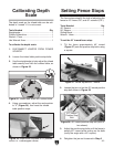
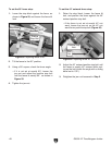
4. Loosen the outfeed table lock located at the
front of the machine, and loosen the jam nuts
and positive stop bolts located at the back of
the machine (see
Figure 47).
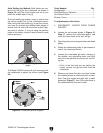
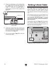
Figure 52. Eccentric bushing and set screw
location.
Eccentric
Bushing
Set Screw
Location
9. Set the outfeed table height (refer to the next
sub-section).
10. Set the knives (refer to Page 35).
11. Reinstall th
e cutterhead guard and fence.


