


-16-
G0656 8" Jointer with Built-In Mobile Base
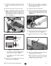
25. Assemble the knife setting gauge using the
knife setting gauge rod, feet and 8mm e-
clips, as shown in
Figure 16.
Figure 16. Knife setting gauge assembly.
Figure 15. Attaching pedestal switch to stand.
24. Thread the excess switch cord through the
access hole in the stand and connect it to the
motor cord.
22. Test the guard by pulling it back and letting it
go.
—The guard should snap back over the
cutterhead without dragging across the
table.
—If the guard drags across the table, loosen
the set screw, raise the guard until it won't
drag, then tighten the set screw.
—If the guard does not snap back, remove it
and repeat
Steps 18–21.
23. Attach the pedestal switch with the cap
screws, lock washers, and flat washers, as
shown in
Figure 15.
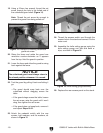
Figure 14. Example of installing cutterhead
guard set screw.
20. Raise the fence and rotate the guard one
revolution counter-clockwise as it appears
from the top. Hold the guard in position.
21. Lower the fence and allow the guard to swing
back against the fence.
NOTICE
The cutterhead guard must always return to
the closed position whenever it is moved.
19. Using a 2.5mm hex wrench, thread the set
screw through the hole in the forked end of
the cutterhead guard shaft (
Figure 14).
Note
: Thread the set screw far enough to
prevent the guard from being pulled out.
26. Replace the rear access panel on the stand.