


-34-
G0656 8" Jointer with Built-In Mobile Base
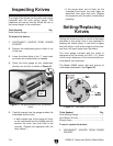
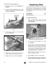
Inspecting Knives
The height of the knives can be easily and quickly
inspected with the knife setting gauge. This
inspection will ensure that the knives are set to
the correct height in the cutterhead.
Tools Needed Qty
Knife Setting Gauge ..........................................
1
To inspect the knives:
1. DISCONNECT JOINTER FROM POWER
SOURCE!
2. Remove the cutterhead guard or block it out
of the way.
3. Lower the infeed table to the
1
⁄2" scale mark
and lower the outfeed table as needed.
4. Place the knife gauge on the cutterhead,
directly over a knife, as shown in
Figure 51.
Figure 51. Gauge positioned over cutterhead
knife.
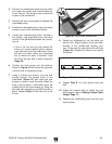
5. Carefully inspect how the gauge touches the
cutterhead and the knife.
— If both outside legs of the gauge sit firmly
on the cutterhead and the middle pad just
touches the knife, then that knife is set
correctly. (Repeat this inspection with the
other knives.)
Middle
Pad
— If the gauge does not sit firmly on the
cutterhead and touch the knife edge as
described, then reset that knife. (
Repeat
this inspection with the other knives before
resetting.)
Figure 52. Cutterhead profile diagram.
Setting/Replacing
Knives
Setting the knives correctly is crucial to the proper
operation of the jointer and is very important in
keeping the knives sharp. If one knife is higher
than the others, it will do the majority of the work,
and thus, dull much faster than the others.
The knife gauge included with the jointer is
designed to set the knives at 0.063" (
1
/16"), which
is the correct distance all the knives should pro
-
trude above the cutterhead.
The Model G0656 comes with jack screws for
cutterhead adjustments (see
Figure 52).
Tools Needed Qty
Knife Setting Gauge .......................................... 1
Hex Wrench 2.5mm ........................................... 1
Wrench 8mm .....................................................
1
To set or replace the knives:
1. DISCONNECT JOINTER FROM POWER
SOURCE!