


G0657/G0658 Benchtop Lathe
-15-
Setup
Before use, the tool rest must be moved out of its
shipping position and centers must be inserted.
For the Model G0658, installing the outboard turn
-
ing attachment is an optional step.
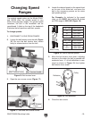
To prepare the lathe:
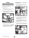
1. Loosen the release lever and rotate the tool
rest base away from the lathe bed.
2. Loosen the tool rest lock handle and rotate
the tool rest so that it is positioned parallel to
the lathe bed (
Figure 9).
Figure 9. Tool rest positioned.
Tool Rest
Lock Handle
Release
Lever
Tool Rest
Base
Tool Rest
3. Tighten the tool rest lock handle.
4. To insert the centers, refer to Installing/
Removing Spur Center and Installing/
Removing Live Center on
Page 21.
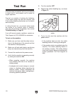
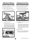
Figure 10. Positioning Handle
To install the outboard turning attachment
(Model G0658 only):
1. Insert one of the lock handles through the
upper slot in the outboard turning attachment,
as shown in
Figure 10.
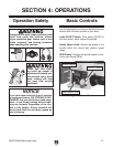
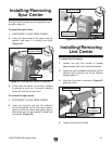
3. Tilt the outboard turning attachment as nec-
essary so the slots line up with the other two
holes in the lathe base, then thread in the
other two handles.
4. Firmly tighten the handles to secure the out-
board turning attachment in position
(Figure
11).
Lock Handle
Outboard Turning
Attachment
Figure 11. Outboard Turning Attachment
Outboard Turning
Attachment
Lock Handles
2. Line up the threaded portion of the handle
with one of the holes in the lathe base, then
thread the handle into the hole. Do not yet
fully tighten the handle.