


-20-
G0657/G0658 Benchtop Lathe
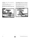
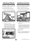
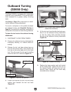
The tailstock is equipped with a cam-action
clamping system to secure it to the lathe bed.
When the lever is engaged, a locking plate lifts
and secures the tailstock to the bed.
To position the tailstock along the bed:
1. Loosen the release lever and move the
tailstock to the desired position (
Figure 20).
Adjusting Tailstock
Figure 20. Tailstock controls.
Release
Lever
2. Re-engage the release lever.
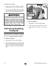
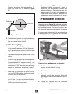
—If the release lever will not lock or release
the tailstock (either too loose or too tight),
loosen or tighten the tailstock mounting nut
(located on the underside of the tailstock)
in small increments as needed to achieve
the proper clamping pressure (Figure 21).
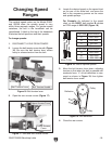
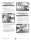
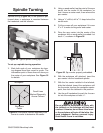
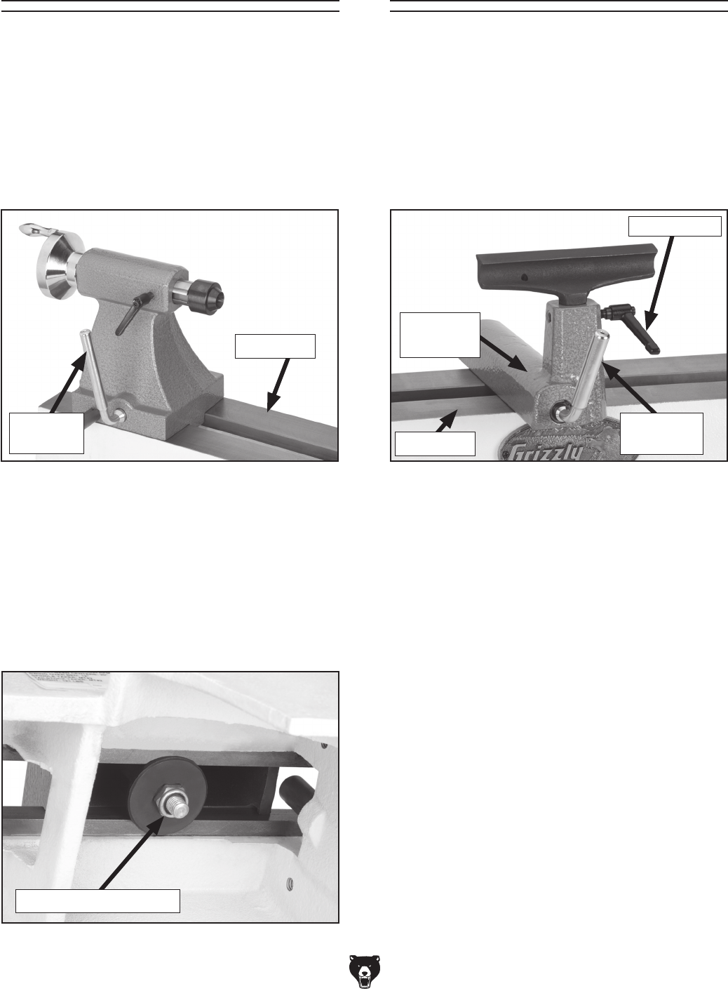
The tool rest base is equipped with a cam-action
clamping system to secure it to the lathe bed.
When the lever is engaged, a locking plate lifts up
and secures the tool rest base to the bed.
To position the tool rest base along the bed:
1. Loosen the release lever and slide the tool
rest base along the bed (
Figure 22).
Adjusting Tool Rest
Figure 22. Tool rest controls.
2. Re-engage the release lever to lock the tool
rest base in place.
— If the release lever will not lock or release
(either too loose or too tight), then loosen
or tighten the tool rest base mounting nut
(located on the underside of the tool rest
base) in small increments as needed to
achieve the proper clamping pressure.
Refer to
Figure 21.
To adjust the tool rest:
1. Loosen the lock handle (Figure 22) and
adjust the tool rest vertically and/or swivel it
as needed, then tighten the lock handle.
Release
Lever
Lock Handle
Lathe Bed
Tool Rest
Base
Lathe Bed
Figure 21. Release lever adjustment.
Tailstock Mounting Nut