


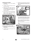

Installing External Wheel
1.
2.
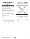
Wheel Inspection & Ring Test
Page 25
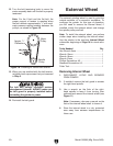
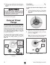
External Wheel Flange
Page 22
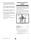
Balancing External
Wheel Page 23
3.
4.
5.
Note: Do not overtighten the wheel nut—this
would make it very difficult to remove the
wheel.
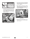
The external grinding wheel represents a
serious entanglement hazard! ALWAYS make
sure the wheel guard is properly installed
before connecting the grinder to power.
6.
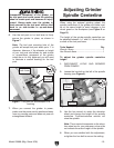
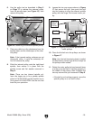
Changing Spindle Pulley & Belt
1.
2.
3.
Figure 14
4.
Note: If the belt is damaged or excessively
worn, replace it with a new one.
5.
Figure 15
Note: The spindle pulley screw has left-hand
threads.
6.
Figure 12
7.
8.
Step 5
9.
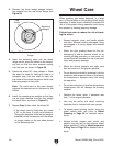
Note: The proper amount of tension is reached
when the belt deflects approximately
1
⁄2" with
moderate pressure applied midway between
the pulleys (see Figure 18).