


G1033 20" Planer -9-
SECTION 4: ASSEMBLY
Overview
Most of your G1033 Planer has been assembled
at the factory, but some parts must be assembled
or installed after delivery. We have organized the
assembly process into steps. Please follow along
in the order presented here.
TOOLS REQUIRED: Most of the tools required
for assembly are included with the planer.
However, you will also need a Phillips
®
and regu-
lar screwdriver, metric wrenches, as well as a
feeler gauge for adjustments.
Extension Rollers
The Model G1033 is supplied with extension
rollers on both the infeed and outfeed ends of the
table. The roller assemblies are identical for both
infeed and outfeed. To attach the extension
rollers:
1. Attach an extension bar to the end of each
roller and secure with the 12mm snap rings
provided.
2. The assembled extension rollers attach to
the ends of the planer’s table. Match the
tapped holes on the side of the table to the
extension bars and attach with the M10 x
1.5 Hex Bolts and washers provided. See
Figure 2.
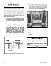
3. Before final tightening, run a straight edge
across the table and past each roller.
Position the rollers flush with the table and
tighten the Hex Bolts securely.
Figure 2. Extension roller attachment.
Extension
Mounting Bolts
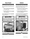
Hand Wheel
The hand wheel operates the chain driven sys-
tem which raises and lowers the table to control
cutting depth. To attach the hand wheel:
1. Place the handwheel on the worm gear
shaft and secure with hex nut and washer
provided. See Figure 3.
2. Attach the handle to the handwheel and
tighten hex nut.
Figure 3. Attaching handwheel.