


-18- G1033 20" Planer
2. Place your test block under the middle of
the chipbreaker (the table should still be at
the same height as it was when you set the
infeed and outfeed rollers).
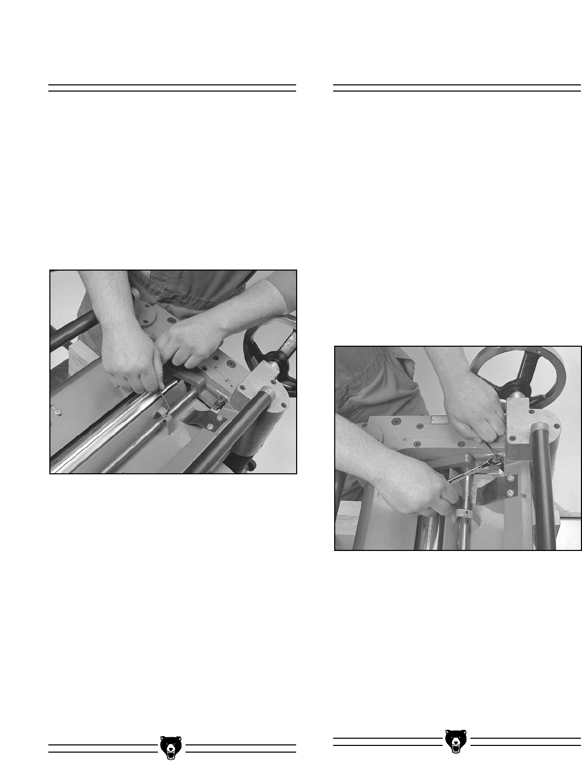
3. Loosen the lock nuts at both ends of the
chipbreaker and turn the setscrews to raise
or lower the chipbreaker as necessary. The
chipbreaker will move evenly, so it does not
matter which setscrew you turn. (You will
need to raise the second setscrew if the
chipbreaker needs to be lowered).
4. When the chipbreaker reaches its proper
height .040'' below the cutterhead height,
tighten the lock nut and adjust the other
setscrew and lock nut to match.
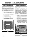
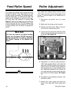
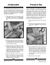
Figure 20. Chipbreaker adjustment.
Chipbreaker
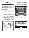
The chipbreaker breaks chips/curls as they are
cut by the cutterhead and forces chips to eject
from the cutting area. Due to its functions within
the planer, the chipbreaker should be adjusted
carefully and checked frequently for movement.
To adjust the chipbreaker:
1. Disconnect planer from its power source
and remove the top cover. Note the location
of the setscrews and lock nuts. See Figure
20.
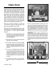
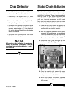
Pressure Bar
Like the chipbreaker, the pressure bar controls
lumber as it passes under the cutterhead. The
pressure bar keeps lumber from lifting after it has
been planed. If the pressure bar is incorrectly
positioned, a number of machining defects
(including snipe and board lines) can result. A
pressure bar set too low can also place excess
load on the planer’s motor. The pressure bar
should be adjusted along with the infeed and out-
feed rollers. To adjust the pressure bar:
1. Disconnect the planer from its power sup-
ply.
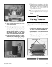
2. Remove top cover. Note setscrew and lock
nut pictured in Figure 21. Loosen the lock
nuts.
3. Place the gauge block under the center of
the pressure bar and adjust the setscrew
until the pressure bar makes slight contact
with the tip of the block. Like the chip-
breaker, the pressure bar can be adjusted
with one setscrew. Make sure to adjust the
second setscrew to match the one you’ve
just adjusted.
4. Tighten the lock nut in place.
Figure 21. Pressure bar adjustment.