


-28-
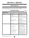
G7947/G7948 12 Speed Floor Drill Press
D
C
B
A
4
3
2
1
4
3
2
1
1 RPM 210
BELT:A-1.4-4
D
C
B
A
4
3
2
1
4
3
2
1
2 RPM 310
BELT:B-2.4-4
D
C
B
A
4
3
2
1
4
3
2
1
3 RPM 400
BELT:A-1.3-3
D
C
B
A
4
3
2
1
4
3
2
1
4 RPM 440
BELT:C-3.4-4
D
C
B
A
4
3
2
1
4
3
2
1
5 RPM 630
BELT:B-2.3-3
D
C
B
A
4
3
2
1
4
3
2
1
6 RPM 670
BELT:A-1.2-2
D
C
B
A
4
3
2
1
4
3
2
1
7 RPM 1260
BELT:D-4.3-3
D
C
B
A
4
3
2
1
4
3
2
1
8 RPM 1430
BELT:C-3.2-2
D
C
B
A
4
3
2
1
4
3
2
1
9 RPM 1650
BELT:B-2.1-1
D
C
B
A
4
3
2
1
4
3
2
1
RPM 2050
BELT:D-4.2-2
D
C
B
A
4
3
2
1
4
3
2
1
RPM 2350
BELT:C-3.1-1
D
C
B
A
4
3
2
1
4
3
2
1
RPM 3300
BELT:D-4.1-1
10
11
12
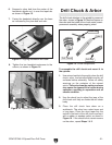
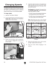
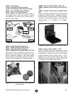
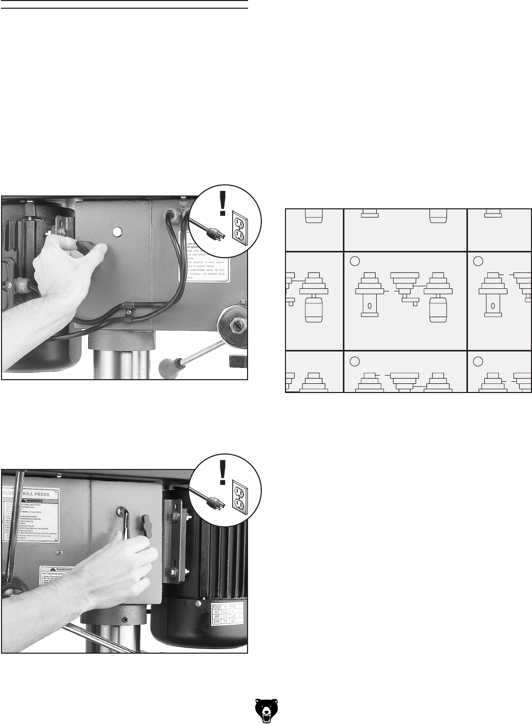
Figure 26. Loosening lock knob (both sides).
Figure 27. Using the belt tension lever.
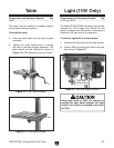
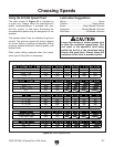
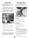
The belts in the head of the drill press must be
rearranged to change speeds. A chart under the
belt cover shows the belt positions needed to
make the drill press run at the desired speed.
To change speeds
:
1. UNPLUG THE DRILL PRESS!
2. Loosen the belt tension lock knobs (shown in
Figure 26) on both sides of the headstock,
so the motor is free to move.
Changing Speeds
3. Rotate the belt tension lever counterclock-
wise, as shown in Figure 27, to take tension
off the V-belts
.
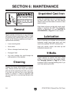
4. Locate the desired speed on the speed chart
under the belt cover and move the V-belts
to the desired V-grooves on the motor, idler,
and spindle pulleys.
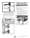
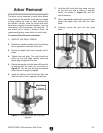
For Example: As indicated in the speed chart
for 670 RPM (Figure 28), a belt combination
of A-1.2-2 creates 670 RPM.
• The “A-1” refers to the belt position between
the spindle pulley and the idler pulley.
• The “
2-2” refers to the belt position between
the motor pulley and the idler pulley.
Note: Both belts may have to be removed
before certain speed changes can be made.
Figure 28. Pulley combination for 670 RPM for
example.
5. Rotate the belt tension lever until the belts
are tight. Tighten both lock knobs.
6. Close the cover before plugging in the
machine.