


Model G8688 (Mfg. 3/09+)
-21-
Ta il s t o c k
The tailstock may be moved along the bedway to
any desired position and locked in position by a
hex nut at its base. The tailstock quill is a MT#2
taper and will hold tools that match that taper,
such as dead center (included), live centers, drill
chucks with arbors, and drill bits with tapers.
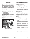
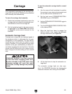
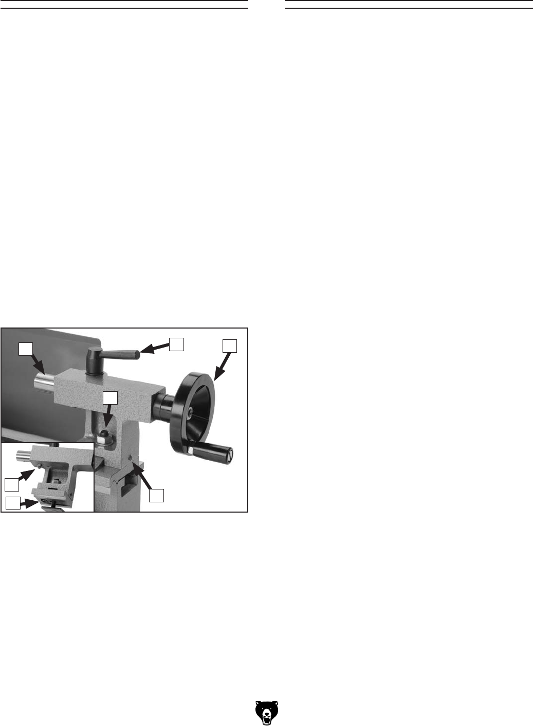
Familiarize yourself with the tailstock components
shown in Figure 18.
A. Quill Lock: Locks the quill in position.
B. Tailstock Handwheel: Moves the quill in and
out of the tailstock.
C. Tailstock Lock Nut: Locks the tailstock in
position to the lathe bed.
D. Offset Setscrew: Helps maintain tailstock
position during tailstock offset adjustment.
E. Quill : Holds tapered tools.
F. Offset Cap Screw : Loosening allows tailstock
offset to be adjusted right or left of center.
G. Quill Gib Screw : Removes play from tailstock
quill.
Tailstock Positioning
Longitudinal Positioning
To adjust the tailstock longitudinally:
1. Using a 17mm wrench, loosen the tailstock
lock nut shown in Figure 18.
2. Slide the tailstock into position along the
bed, then tighten the clamp nut to secure the
tailstock in the new position.
Offset Positioning
Changing the tailstock offset is a common meth-
od for turning tapers. The offset cap screw is
located under the tailstock and the tailstock
must be removed from the bed for this adjust-
ment. Therefore, precision tolerances for this type
of work will require trial-and-error adjustments
(Figure 18).
To offset the tailstock:
1. Loosen the tailstock lock nut with a 17mm
hex wrench and slide the tailstock off the
lathe bed.
2. Loosen the offset cap screw just enough so
the tailstock can slide.
3. Slide the tailstock back onto the bed, then
adjust to the desired offset.
4. Tighten the setscrew to hold the tailstock in
position.
5. Carefully slide the tailstock off of the bed,
then tighten offset cap screw.
6. Slide the tailstock back onto the bed, lock it in
position and recheck your setting.
7. Repeat these steps as often as needed to
obtain your desired results.
8. For re-alignment refer to Page 36.
Figure 18. Tailstock controls.
D
E
F
G
A
B
C