


-26-
Model G8688 (Mfg. 3/09+)
The Model G8688 can be geared for a variety of
different feed rates, so a chart is placed on the
drive cover of the lathe that explain how to set up
the gear combinations for threads per inch. The
chart for metric thread pitches is included in the
manual. See Figure 27 for reference.
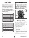
Threading Chart: By arranging the gears as
shown on the threading charts (see Figures 25
– 26), you can set up the automatic carriage feed
to cut any of the threads per inch (TPI) or metric
thread pitches indicated.
Gear Charts
TPI GEARS TPI GEARS
A B C D A B C D
12 40 65
⁄
30 26 40 60
⁄
65
13 40 65 60 30 28 20 65
⁄
35
14 40 65
⁄
35 32 20 65
⁄
40
16 40 65
⁄
40 36 20 65
⁄
45
18 40 65
⁄
45 38 20 50 60 57
19 40 50 60 57 40 20 65
⁄
50
20 40 65
⁄
50 44 20 65
⁄
55
22 40 65
⁄
55 48 20 65
⁄
60
24 40 65
⁄
60 52 20 60
⁄
65
Figure 25. Threads per inch chart (TPI).
mm/
pitch
Gear
A B C D
0.4 20 50 40 60
0.5 20 50 ⁄ 60
0.6 40 50 30 60
0.7 40 50 35 60
0.8 40 50 40 60
1.0 20 60 ⁄ 30
1.25 50 40 ⁄ 60
1.5 40 60 ⁄ 40
1.75 35 60 ⁄ 30
2.0 40 60 ⁄ 30
Figure 26. Metric thread pitch chart.
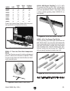
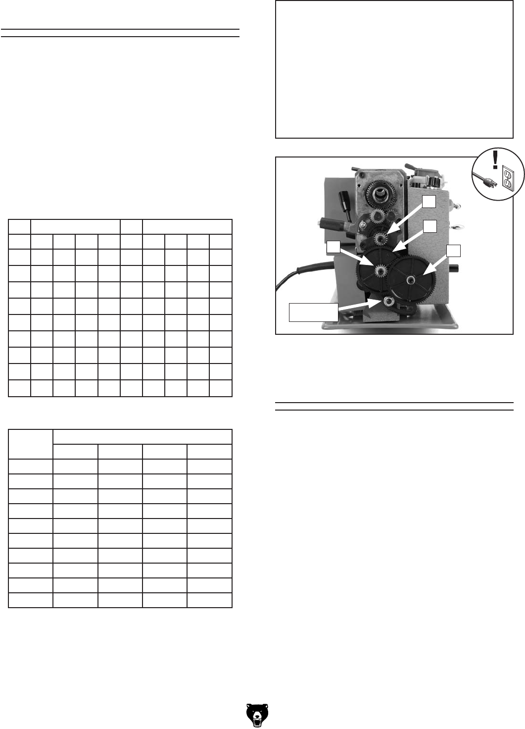
Figure 27 shows the locations of the gears refer-
enced in the gear charts Figures 25 & 26.
For example if you wanted to cut a
1
⁄2" x 13
thread on a piece of round stock.
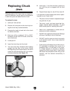
1. UNPLUG THE LATHE!
2. Remove the gear cover.
3. Loosen the adjuster to disengage the gears
from each other.
4. Remove the gears in place and replace with
the 40, 65, 60, & 30 tooth gears in the called
out positions.
5. Position the adjuster so the gears mesh.
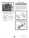
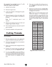
NOTICE
There are many details to thread cutting
and other lathe operations. It is not within
the scope of this manual to cover detailed
information regarding types of cutting tools,
cutting speeds and working with different
types of metal. If you do not have training
in this area you MUST seek training from a
qualified person before proceeding!
Figure 27. Gear positions.
A
D
C
B
Adjuster
Change Gears