


-12- Ultimate Series Jointers
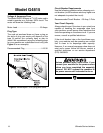
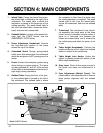
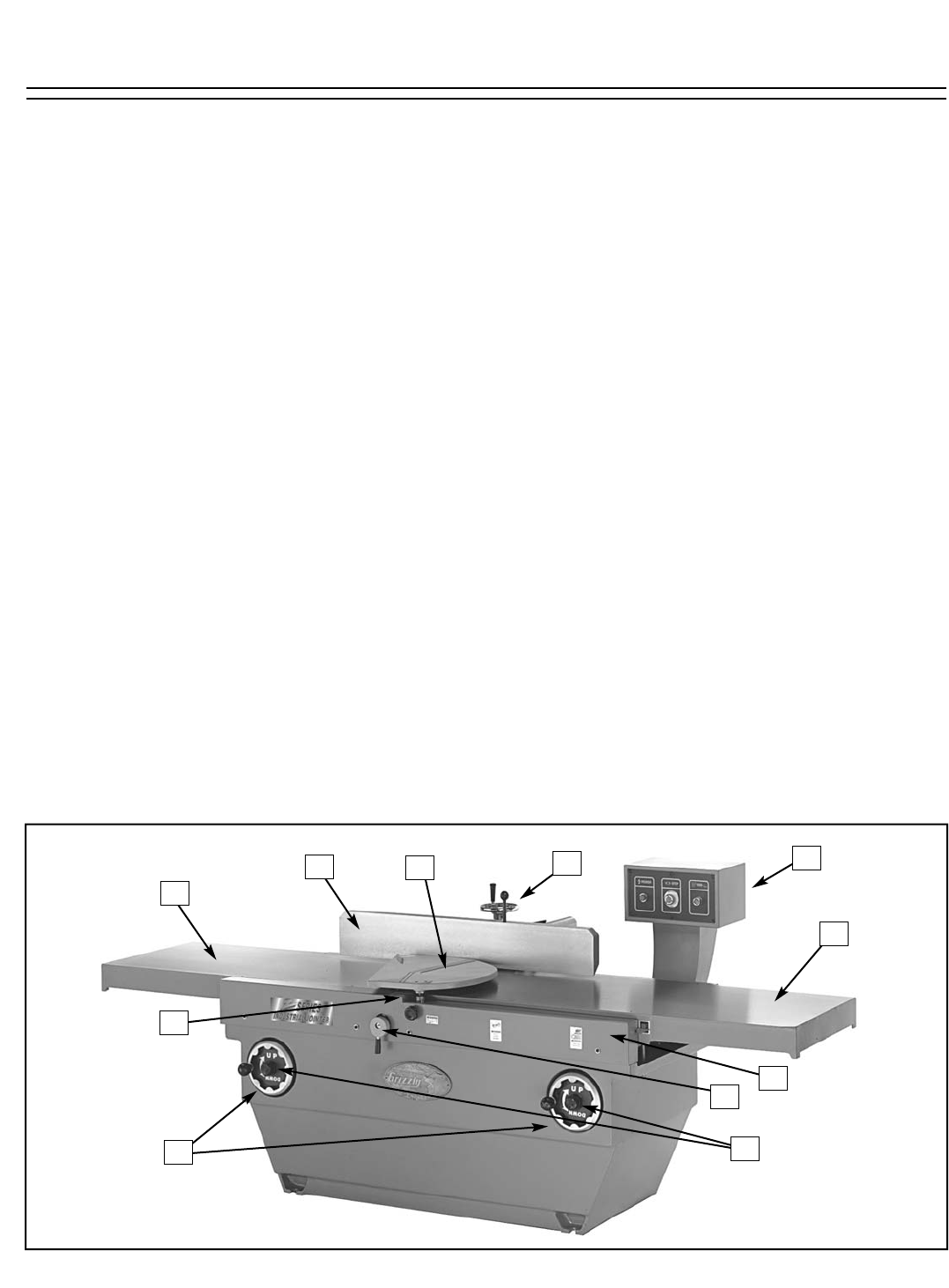
1. Infeed Table: Facing the front of the jointer,
the infeed table is located to the right of the
cutterhead. The infeed table is where the
workpiece is placed at the beginning of the
cutting operation. The wood travels right to
left; from the infeed table, across the cutter-
head, and onto the outfeed table.
2. Pedestal Switch: Location of the power indi-
cator light, the START button, and the
EMERGENCY STOP button.
3. Fence Adjustment Handwheel: Controls
the back-and-forth location of the fence
across the top of the tables.
4. Cutterhead Guard: Orange, spring-loaded
safety cover that retracts over the cutterhead
when the workpiece is NOT passing over the
jointer.
5. Fence: Surface the workpiece guides along
when jointing or surface planing. The fence
can be positioned 45˚ and 90˚ to the surface
of the tables to accommodate either bevel or
right-angle jointing operations.
6. Outfeed Table: Facing the front of the joint-
er, the outfeed table is located to the left of
the cutterhead. The outfeed table is where
the workpiece is lifted from the jointer after
the cutting operation is complete. The wood
travels right to left; from the infeed table,
across the cutterhead, and onto the outfeed
table.
7. Cutterhead: The cutterhead is the cylindri-
cal assembly that holds each of the three
jointer knives or indexable carbide cutters. It
spins on a horizontal axis between the
infeed and outfeed table, and is covered by
the cutterhead guard when the jointer is not
in use.
8. Table Height Handwheels: Controls the
height positioning of the infeed and outfeed
tables in relation to the cutterhead.
9. Table Height Lock Knobs: Knobs that
tighten to prevent accidental rotation of the
table height handwheels.
10. Stop Lever: Shuts off the power source to
the jointer and slows the cutterhead to a
stop.
11. Cam Adjustment (Behind Cover): The
infeed table is fully adjustable with 4 cams to
allow perfect alignment with the outfeed
table.
Model G4815 Shown
1
2
3
4
5
6
7
8
9
11
10
SECTION 4: MAIN COMPONENTS