


Ultimate Series Jointers -33-
The models with spiral cutterheads are supplied
with an air wrench for loosening and tightening
the carbide cutter Torx® screws. This tool is very
valuable if you have to rotate or change many of
the cutters at one time. T-20 Torx® bits are
included.
Installing or adjusting the carbide cutters:
1. Connect the air wrench to your regulated air
compressor.
2. Adjust the air pressure (torque) setting dial on
the side of the air wrench to the "2" position.
Note—The "1, 2, 3" dial on the air wrench
adjusts the torque, relative to the compressor
air pressure. The "1" setting will produce the
highest amount of torque possible at a given
compressor air pressure, while the “3” setting
will produce the least torque.
3. Install a T-20 Torx® bit into the air wrench.
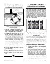
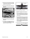
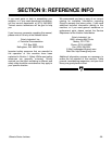
Carbide Cutters
(Models G9953ZX, G9953ZXF and G4815)
The dot on each cutter is used as a reference
point when determining which cutter edges are
used, or dull, and which are sharp. Be sure to
always rotate the cutters is the same direction as
shown in Figure 37. Otherwise, the dot will not be
an effective reference for determining which cut-
ting surfaces are sharp. The carbide cutter dimen-
sions are 14mm x 14mm x 2mm, with a 6.5mm
bore and 30° relief angles.
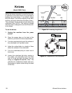
8. Rock the cutterhead back-and-forth, using
the cutterhead pulley to position the knife
edge at the highest point in its revolution.
9. Using a 3mm allen wrench, find the jack
screws through the access holes in the cut-
terhead and rotate the jack screws to raise or
lower the knife. When the knife is set correct-
ly, it will barely touch bottom of the knife set-
ting gauge WITHOUT lifting the gauge off the
outfeed table. Note—The knife height should
be level with the outfeed table to within .002".
A dial indicator can be used to check varia-
tion in thousandths of an inch; however, the
knife setting gauge is an adequate setup
instrument.
10. Snug the gib bolts tight enough to just hold
the knife in place.
11. Repeat steps 5-10 with the rest of the knives.
12. Repeat step 10, but final tighten each gib
bolt.
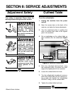
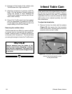
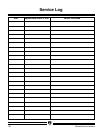
Outfeed Table
Figure 36. Checking knife with the
knife setting gauge.
Knife Edge At
Highest Point
Of Rotation
Knife Setting
Gauge
7. Position the knife setting gauge on the out-
feed table so that it extends over the cutter-
head as shown in Figure 36, and loosen the
gib bolts until the knife is completely loose.
Figure 37. Always rotate carbide cutters in the
same direction to keep track of the dull or
damaged edges.
Reference Dot