


G9958 4 H.P. Dust Collector -15-
4. Gradual directional changes are more efficient
than sudden directional changes (i.e. use the
largest corner radius possible when changing
hose or pipe direction).
5. Each individual machine should have a blast
gate to control suction from one machine to
another.
6. The simpler the system, the more efficient and
less costly it will be.
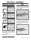
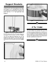
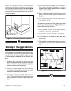
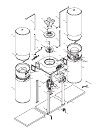
The best way to plan your new system is to draw
a bird’s eye view (as shown in
Figure 14)
of your
shop and sketch the following:
1. Your desired location of the dust collector,
usually in a corner or along a wall.
2. The location of each machine in the system.
3. The location of the main line duct and each
branch line.
4. The location of any obtrusion such as a joist or
heating duct, that will require special duct rout-
ing.
When designing a successful dust collection sys-
tem, planning is the most important step. Before
you set out to run the first section of duct, consid-
er these general guidelines for an efficient sys-
tem:
1. Machines that produce the most saw dust
should be placed nearest to the dust collector.
These machines include thickness planers,
shapers, sanders and bandsaws.
2. Ideally you should design the duct system to
have the shortest possible mainline run and to
have short secondary branch ducts.
3. Directional changes should be kept to a mini-
mum. The more directional change fitting you
use, the greater the loss of overall static pres-
sure.
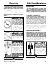
Design Suggestions
Figure 13. Flex-hose grounded to machine.
Ground Screw
Flex-Hose
Internal Ground Wire
External Ground Wire
Figure 14. Bird’s eye planning view.
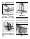
Attach the bare ground wire to each stationary
woodworking machine and attach the dust collec-
tor frame with a ground screw as shown in Figure
13. Ensure that each machine is continuously
grounded to the grounding terminal in your elec-
tric service panel.
Main Line
Collector
Branch Line
Dust