


-12-
Model T25100 (Mfg. Since 8/12)
Basic Controls &
Components
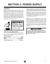
Use Figures 5–7 and the following descriptions to
gain a better understanding of the Model T25100
controls and components.
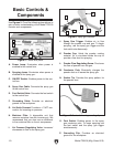
Figure 5. Control box panel.
A
B
C
D
E
F
A. Power Lamp. Illuminates when power is
enabled to the control box.
B. Spraying Lamp. Illuminates when power is
enabled to the spray gun.
C. ON/OFF Switch. Enables power to the con-
trol box.
D. Spray Gun Cable. Connects the spray gun
to the control box.
E. Foot Switch Cable. Connects the foot switch
to the control box.
F. Grounding Cable. Provides an electrical
ground for the workpiece.
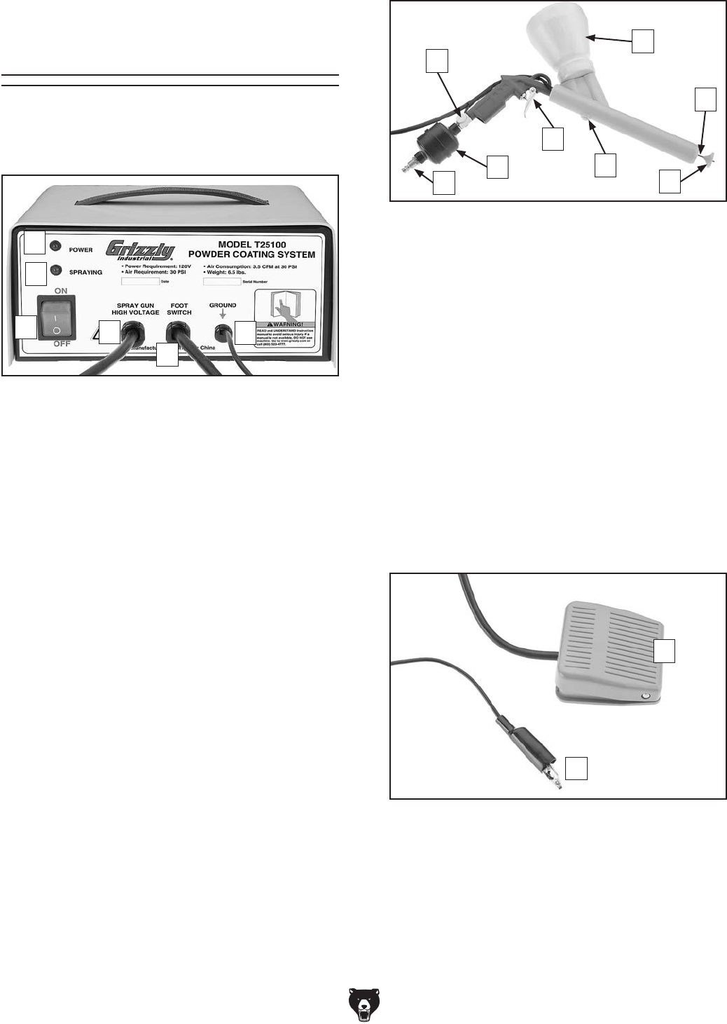
G. Air Quick-Connect. Provides a
1
⁄4" NPT con-
nection for incoming air pressure.
H. Moisture Filter. A disposable unit that
removes moisture from the incoming air. We
recommend that you also use an additional
in-line moisture filter on the air compressor.
I. Air Pressure Regulating Valve. Increases/
decreases air flow to the spray gun.
J. Spray Gun Trigger. Enables air to flow
through the powder cup and gun. To begin
spraying, use the spray gun trigger and the
foot switch simultaneously.
K. Powder Cup. Holds the powder coating
material. Air is circulated inside the cup to
provide a fine dust for spraying.
L. Powder Flow Regulating Screw. Fine tunes
the flow of powder from the gun.
M. Conductor Pole. Electrically charges the
powder dust as it leaves the spray gun.
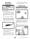
N. Scatter Tip. Provides the spray pattern for
the powder dust.
Figure 7. Foot switch and grounding clip.
O
P
O. Foot Switch. Enables power to the spray
gun conductor pole. To begin spraying use
the foot switch and the spray gun trigger
simultaneously.
P. Grounding Clip. Provides an electrical
ground for the workpiece.
Figure 6. Spray gun controls.
J
K
N
M
G
H
I
L