


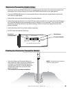
Wireless Exit Sensor
7
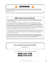
Programming the Exit Sensor’s Transmitter Code
Beforeuse,thereceiverneedsto“learn”thecodetransmittedbythewirelessexitsensor.Thissimpleprocedure
takesonlyafewminutes.
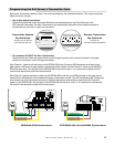
• Gen3(blueboard)instructions
Setthe9DipSwitchesintheTransmitterModuletothesamesettingsasthe9DipSwitchesinthe
GTORemoteTransmitter.TheGen3(blueboard)willautomaticallyrespondtothewirelessexitsensor’s
transmissionasafreeexitoropenonlycommand.
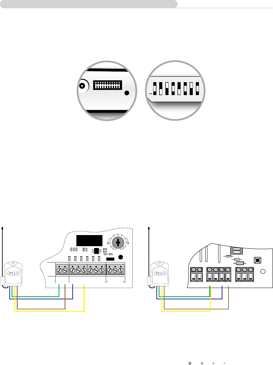
• ForoperatorsWITHOUTtheGen3(blueboard)
Disconnectthered,blackandgreenwiresfromtheoriginalreceiveratthereceiverterminalsonthegate
opener’scircuitboard.Itwillnolongerbeneeded.
WireChannel1(greenandbluewires)ontheRB709U-NBtotheCycleandCOMaccessoryterminalsonthe
gateopener.Holddownthegateopener’sremotetransmitterbuttonandtheChannel1buttonontheRB709U-
NBatthesametime.TheredlightontheRB709U-NBshouldblinkoncein1to2secondstoindicatethatthe
receiverhaslearnedthecodefromtheexitsensor.
WireChannel2(yellowandbrownwires)ontheRB709U-NBtotheExitandCOMterminalsonthegateopener.
InstallthetwoAAbatteriesinthewirelessexitsensor’stransmittermodule.Thiswillimmediatelystart30seconds
oftransmissionsfromthewirelessexitsensor.Whiletheexitsensoristransmitting,holddowntheChannel2
buttonontheRB709U-NB.TheredlightontheRB709U-NBshouldblinkoncein1to2secondstoindicatethat
thereceiverhaslearnedthecodefromtheexitsensor.
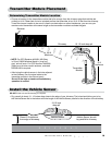
Transmitter Module
Dip Switches
SetSameAsGTORemote
TransmitterDipSwitches
Remote Transmitter
Dip Switches
SetSameAs
TransmitterModuleDipSwitches
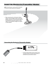
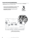
PRO3040-PCB Connections GTO/PRO1000, SL1000/2000 Connections
ON
ALARM ACCESSORY RCVR
SEQ1
SEQ2
LEARN
BLU
ORG
WHT
GRN
R B G
CH 1 (Green Wire to Grn)
CH 1 (Blue Wire to Blu)
CH 2 (Yellow Wire to Grn)
CH 2 (Brown Wire to Wht)
CH 1 (Green Wire to Com)
CH 1 (Blue Wire to Cycle)
CH 2 (Yellow Wire to Exit)
CH 2 (Brown Wire to Com)
RECEIVER
COM COM
CYCLE
CLOSE
SAFETY
EXIT/
OPEN
SHADOW
LOOP
CLOSE
EDGE
OPEN
EDGE
BLKGRN RED
STALL FORCE
M
I
N
M
A
X
GTO WIRELESS EXIT WAND
TRANSMITTER
CODE
TRANSMIT
ACTIVE
MIN MAX
SENSITIVITY
+
0
ECE
1 2 3 4 5 6 7 8