


Step 8) Secure the rear table in position and remove the feeler gauge.
Step 9) Lower the infeed table and place a straight edge on the outfeed table so that it
extends out over the cutterhead.
Step 10) Turn the cutterhead by hand until the knife is at its highest point at each end of the cutterhead.
Using the wrench, turn the screw clockwise until the knife just touches the straight edge on
each end and at the center. Once the knife is fully adjusted, again tighten the four locking
screws.
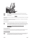
Sharpening the Knives
Step 1) Use a fine grade Carborundum stone. Cover the bottom portion of the stone with
paper. The top portion will touch the knife, and the paper will keep the stone from
scratching the table.
Step 2) Lay the stone on the infeed table. Lower the table and turn the cutterhead until the stone lies
flat on the edge of the knife. Sharpen the beveled edge of the knife by sliding the stone back
and forth across the table. Repeat for each additional knife.
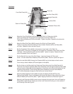
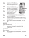
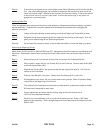
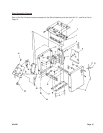
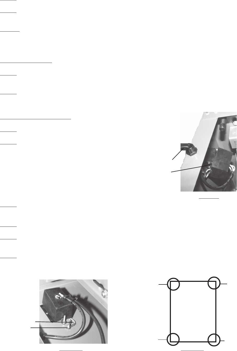
Wiring the Jointer-On and OFF
Step 1) Insert the Switch Box through the hole in the Stand (#69).
Step 2) Insert the wires through the hole in the Switch Box-
see Figure 9.
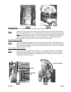
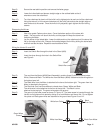
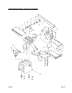
Step 3) The cord from the Motor (#29A-Stand Assembly) contains three (3) different colored wires;
White, Green and Black. The White wire from the Motor (#29A) is attached to the wiring box on
the bottom lower left.
Step 4) The Black Wire from the Motor is attached to the box at the bottom right. The green from the
Motor is attached to the ground.
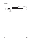
Step 5) The Electrical Cord has three different colored wires; Green, White and Black.
The white wire is to be attached to the box at the top left. The Black is to be
attached to the top right. The green wire goes to the ground.
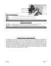
Step 6) The ground is the lower screw as shown in Figure 10. The lower screw is inserted through the
Jointer and is tightened into place by sliding on a Lock Washer and then a Nut. Do not tighten
into place until both green wires are attached to the ground-see Figure 10 and 12.
Outlet
Switch Box
Figure 9
Ground
Green Wires
White from Outlet
White from Motor
Black
From Cord
Black From Motor
Figure 10 Figure 11
#31849 Page 11