


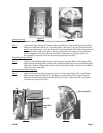
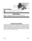
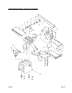
Step 9) Attach the Tapping Plate (#25A) with Right and Left
Tapping Fenders (#23A & #27A) to the Left Protecting
Plate (#26A). Insert the Screws (#17A) with head on the
outside of the Plate. On the inside, slide on Washer
(#7A) and Nut (#6A)-see Figure 2.
Step 10) Attach the Reinforcing Plate (#3A) to the Roof ( #1A)
on the same side as the Left Protecting Plate
using Screws (#17A), Washers (#7A) and Nuts (#6A).
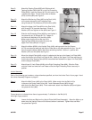
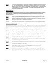
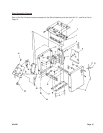
Step 11) Attach the Upper Link Plate (#2A) to the Roof (#1A)
with Screw (#17A) inserted downward. Slide on
Washer (#7A) and tighten on Nut (#6A)-see Figure 1.
Step 12) Slide the Left Protecting Plate (#26A) on and tighten it
into place with six (6) Screws (#17A). Fasten on
the inside with Washers (#7A) and Nuts (#6A).
Make certain that the lips at the top of the
Tapping Plate (#25A) are positioned under the
Upper Link Plate (#2A) as in Figure 1.
Step 13) Attach the Motor (#29A) to the Upright Plate (#4A) making certain that the Screws
(#17A) are placed at least half way up the Plate (#4) on the side opposite the lips. You will
have to move the Motor (#29A) later when tensioning the Belt. Secure in position with
Washer (#7A) and Nut (#6A)-see Figure 1.
Step 14) Mount the Upright Plate (#4A) so that it is attached at the top to the Upper Link Plate (#2A)
and at the bottom to the Side Link Plate (#19A). Attach to the Upper Link Plate making sure
that the lips of the Tapping Plate (#25A) are sandwiched between the Upper Link Plate (#2A)
and the Upright Plate (#4A).
Step 15) Attach three (3) Lock Plates (#24A) to the Right Protecting Plate (#8A). Slide the Plate
onto the Frame and twist the Lock Plates so that the Right Protecting Plate is securely in
position.
Jointer Assembly
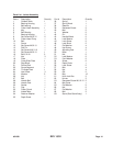
Each of the following part numbers, unless otherwise specified, are from the Jointer Parts List on page 14 and
the Jointer Assembly Diagram on page16.
Step 1) Attach the Belt Cover (#64) to the Stand (#69). Make certain that the Belt (#10) is
in place on the Center Head Pulley (#9). Insert Recessed Screw (#63) through
each foot of the Belt Cover (#64). From underneath, attach Lock Washer (#65) and tighten
into place with Nut (#66).
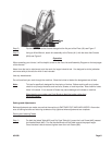
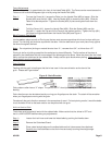
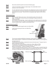
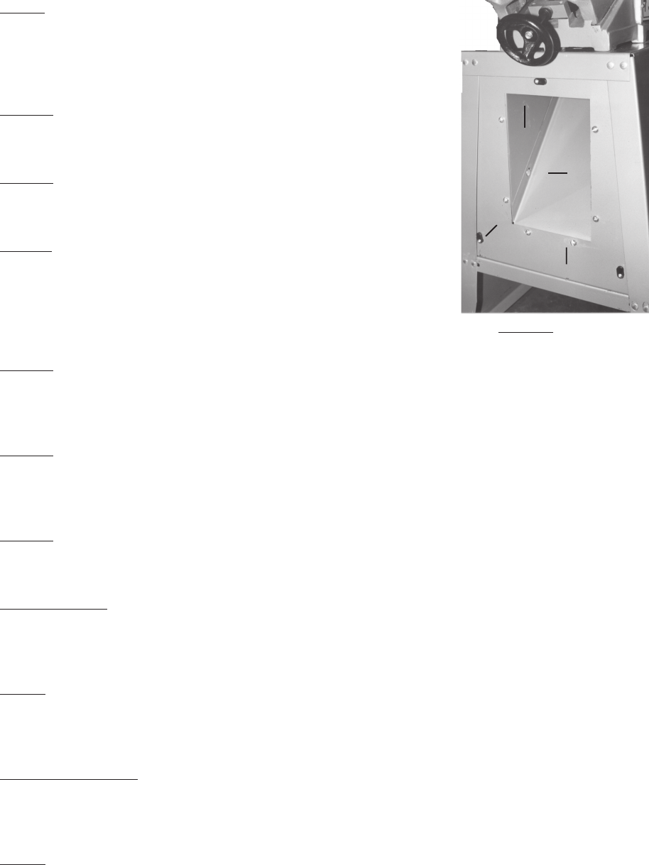
Adjusting Belt Tension
Correct tension is indicated when there is approximately 1" deflection in the Belt (#10)
with slight finger pressure.
Step 1) Loosen the Nuts and Bolts on the Upright Plate (#4A-Stand Assembly). Move the Motor up or
down along the Upright Plate until the correct tension is achieved. Tighten Nuts and Bolts
into place-see Figure 3.
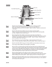
Figure 2
Tapping Plate (#25A)
Left Tapping Fender (#27)
Lock Plate (#24A)
#31849 Page 6
Left Protecting Plate (#26A)