


The Stand
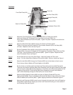
Step 1) Attach the Front Side Plate (#16A) to both of the Side Link Plates (part #19A).
Insert two Screws (#17A) through Front Side Plate and through Side Link
Plate. Slide on Washers (#7A) and Nut (#6A). Tighten into place. Repeat for the other side
- see Figure 1.
Step 2) Attach the Rear Side Plate (#30A) to each of the Side Link Plates (#19A).
Tighten it into place with two Screws (#17A) and attach Washers (#7A) and Nuts (#6A)
on inside. Repeat for other side-see Figure 1.
Step 3) Set the Crossbeam Plate (#18A) so that it sits on top of each of the Side Link
Plates (#19A). Insert two (2) Screws (#17A) through the Crossbeam Plate (#18A) and Side
Link Plate. Slide on Washers (#7A) and Nuts (#6A). Tighten into place. Repeat for other
end of Crossbeam Plate- see Figure 1.
Step 4) Set the Roof (#1A) on top of the Side Plates. Insert two Screws (#17A) at each
corner. On the inside slide on Washer (#7A) and Nut (#6A). Secure in place-see Figure 1.
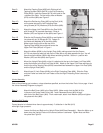
Step 5) Attach the foot Bolt (#22A) through the Chassis (#20A) and to the bottom of each corner.
From the top, slide on Washer (#7A) and tighten on Nut (#6A).
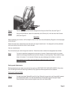
Step 6) Set the Jointer on the Stand with the Cutterhead Guard facing the Front SidePlate (#16).
There are two holes for the Bolts (#68-Jointer Assembly) over the Right Protecting Plate (#8A)
and one hole for a Bolt (#68-Jointer Assembly) in the center of the Roof (#1A) above the Left
Protecting Plate (#26A). Slide the Bolt (#68-Jointer Assembly) through the flat Washer
(#67-Jointer Assembly) through the Roof (#1A) and into the Jointer.
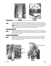
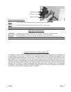
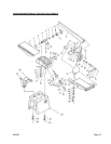
Step 7) Attach the Right Tapping Fender (#23A) and the Left Tapping Fender (#27A) to the
Tapping Plate (#25A). Insert Lock Washer (#21A) with the head on the outside of the Stand.
Slide on Washer (#7A) and Nut (#6A). Tighten Tapping Fenders onto Plate-see Figure 2.
Step 8) Attach a Lock Plate (part #24A) to each corner hole and to the top hole in the Left Protecting
Plate (#26A). Make certain that the part of the Lock Plate with the wing is on the outside of
the Protecting Plate-see Figure 2.
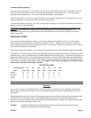
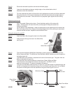
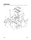
Front Side Plate(16A)
Side Link Plate(19A)
Motor (29A)
Rear Side Plate (30A)
Crossbeam Plate (18A)
Roof (1A)
Figure 1
Upright Plate (4A)
#31849 Page 5