Cutterhead Guard
Warning: Beware of sharp blade when installing the Cutterhead Guard.
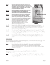
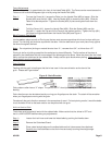
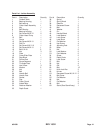
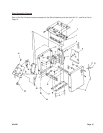
Step 1) Inside of the Spring Knob (#37) there is a Spring (#36) which returns the Guard toits position
above the Cutterhead after a cut. To create tension in the Spring, turn the Spring Knob (#37)
before inserting the post. Insert the Post of the Cutterhead Guard (#32) down through the hole
in the Infeed Table (#33)-see Figure 4. When inserting the Post, make sure that the Spring
(#36) is engaged in the slot at the end of the Post. The tension on the Spring (#36) can
be changed by removing the Guard and turning the Spring Knob (#37).
Assembling Handle Wheels
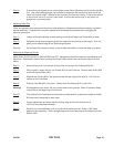
Step 1) There is a Handle Wheel (#43) located on each side of the Base (#50). With Adjusting Pole
(#49) inserted into Base (#50), make certain Lock Block (#46) sits on top of the Adjusting Pole.
Insert Bolt (#40) into Washer (#41) and through Handle Wheel (#43). Screw into Lock Washer
(#44) and Lock Screw (#45).
Fence and Angle Scale Assembly
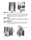
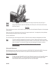
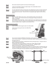
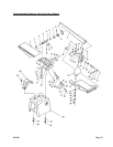
Step 1) Insert the Fence Plate (#18) through the hole in the Cross Slide Plate (#19). Insert Washer
(#25) and Nut (#26) onto Bolt (#27). Add Washer and slide Bolt (#27) through Plate (#18).
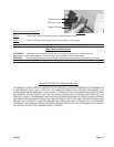
Attach the Handle Pole (#29) and Socket (#30) over the Nut. Attach Cap (#31) and tighten
into place-see Figures 5, 6 and 7.
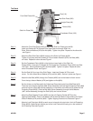
Figure 3 Figure 4
Washer (25)
Nut (26)
Socket (30)
Bolt (27)
Figure 5
Jib
Hex Screw (#24)
Figure 6
Handle Pole
(29)
#31849 Page 7


