


Page 10SKU 37793 For technical questions, please call 1-800-444-3353.
Tighten the Lock Lever.
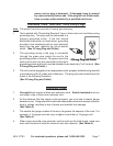
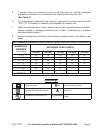
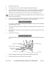
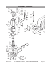
Turn Stopper (57) turret to select the desired Hex Bolt (65) height.
Lower the Screw (32) stopper pole until it touches the adjustable Hex Bolt (65).
Press and hold the Half Nut (18) fast feed button to lower stopper pole rapidly.
Raise the Screw (32) stopper pole in ne increments to desired depth of cut.
Note: The depth of cut is equal to the distance between the end of the Screw (32) and
the top of the Hex Bolt (65).
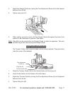
Loosen Lock Lever (26) and lower router body until Screw (32) stopper pole makes
contact with the Hex Bolt (65). The depth of cut can now be seen.
Upper Limit Adjustment
The upper limit adjustment should be set so that the bit clears the stock material
by approximately 1/2 inch.
Turn the Knob (68) to the correct upper limit and clamp in place using the Lock
Lever (26).
Screw the Nut (70) down the screw shaft until it seats rmly against the motor
housing (5).
Loosen the Lock Lever.
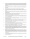
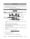
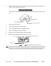
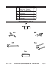
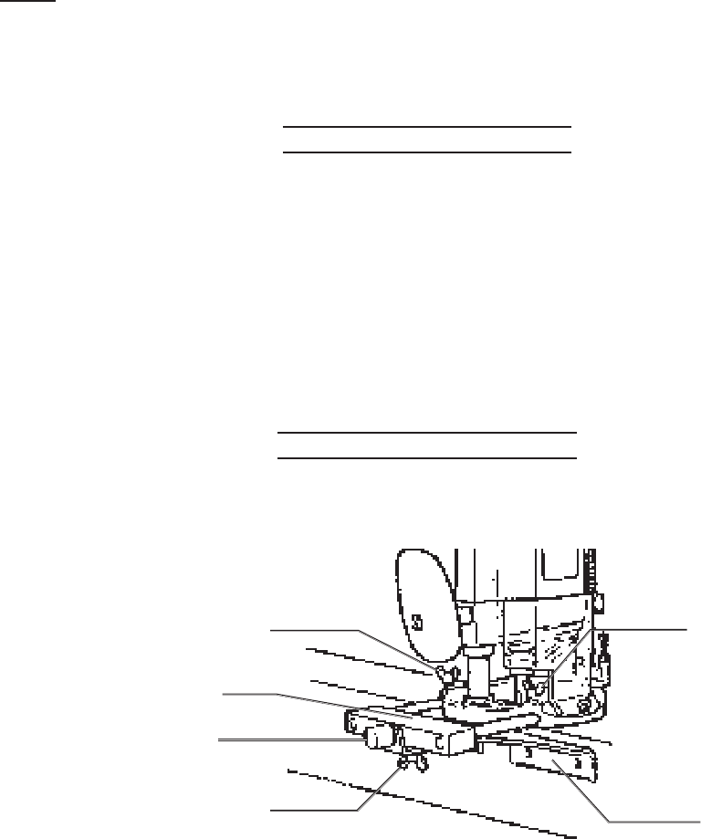
Using the Straight Guide
The Straight Guide (4A) and Guide Holder (6A) are used for chamfering or grooving
cuts.
Guide Holder (6A)
Guide (4A)
Fine Adjustment
Screw (A)
Wing Nut (B)
Wing Nut (C)
Wing Nut (C)
Place the Straight Guide on the Guide Holder with the Wing Nut (B).
Insert Guide Holder into the holes in the router base.
4.
5.
6.
7.
8.
1.
2.
3.
1.
2.