


For technical questions, please call 1-800-444-3353.SKU 38123 Page 12
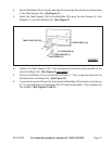
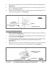
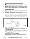
AUXILIARY
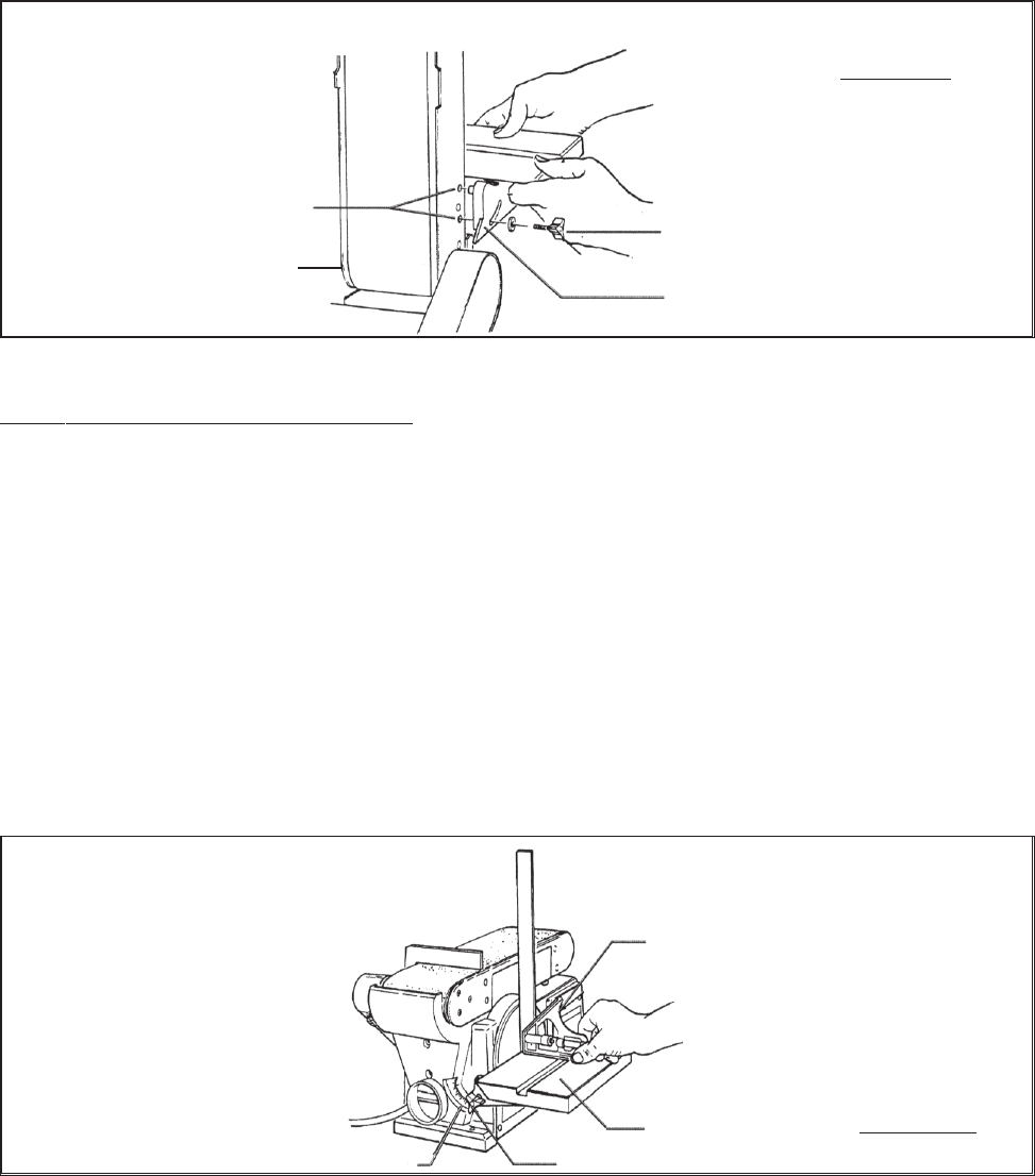
MOUNTING HOLES
KNOB (1)
TABLE SUPPORT (36)
HEX SOCKET SCREW (56)
(NOT SHOWN)
FIGURE I
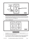
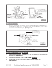
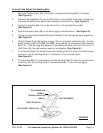
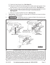
To Level The Worktable Assembly:
1. Place a combination square on the Worktable (35) so that the square also touches the
Sanding Pad (27). (See Figure J.)
2. If the Worktable (35) is 90 degrees to the Sandpaper Pad (27), the combination square
is flush on the Pad. (See Figure J.)
3. If the Worktable (35) is NOT 90 degrees to the Sandpaper Pad (27), loosen the Knob
(1) and tilt the Worktable until the combination square is flush with the Pad.
(See Figure J.)
4. Retighten the Knob (1) to secure the Worktable (35) in place. Then, attach the Scale
Label (37) to the “0” degree mark on the Dust Collector (34). (See Figure J.)
4. Loosen the Hex Socket Screw (56), and raise the Bed (4) to the desired sanding position.
(See Figure I.)
5. Insert the Index Pins of the Table Support (36) into the Auxiliary (upper) Holes in the
Bed (4). (See Figures G and I.)
6. Retighten the Hex Socket Screw (56). Check to make sure the Worktable (35) is not
touching the Sanding Belt (10). (See Figure I.)
SCALE LABEL (37) KNOB (1)
WORKTABLE (35)
COMBINATION SQUARE
(NOT INCLUDED)
FIGURE J