COMPLETING ASSEMBLY
WARNING: Be sure the machine is unplugged before attempting any assembly or adjustment operation.
Attaching the Carrying Handles
1. Locate the two carrying handles (#349), and their hardware, Screws (#327).
2. Attach the handles to the top of the machine using the screws. Be sure the handles are firmly attached.
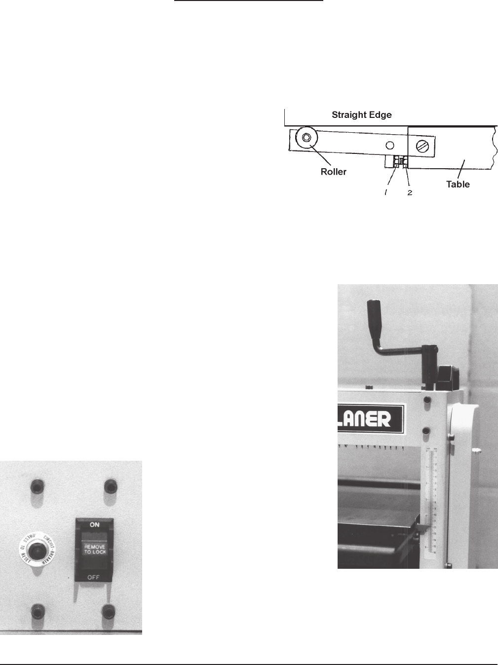
Installing the table extensions
1. With the roller up, place each table extension bracket
(#157) onto the table (#125) and attach using two
cap screws (#164). Be sure the bracket assemblies are
firmly attached, but are able to rotate up for storage.
2. Adjust each table extension so that a workpiece
supported by the roller is level and in the same plane
with the table. Do this by adjusting the cap screws
(#1) in or out as required. See Figure 2. Check
the adjustment by placing a straight edge at least 24” long through the machine, and resting on the table
and both extension rollers. When the extension is properly adjusted, lock the cap screws in place with
the lock nuts (#2).
Setting the Cutting Depth
1. Place the Table Adjustment Handle (#150) over the square-ended
Control Screw (#130) which protrudes throught the top of the machine.
2. Turn the Table Adjustment Handle to raise or lower the Table to
the desired cutting thickness.
3. Read the cutting depth reading on the scale on the right of the
machine.
4. Remove the Table Adjustment Handle before operating the machine.
Operating the Power Switch
1. The power switch is located on the lower right front of the machine.
2. The Safety Switch Cover may be installed or removed by pressing
it onto or pulling it off of the power switch.
3. The Safety Switch Cover must be
in place to operate the Power Switch.
You can remove the Cover and store it in
a safe place to prevent unauthorized use
of the machine.
4. Press the Switch UP to turn the
machine ON, and DOWN to turn the
machine OFF.
Integral Circuit Breaker.
1. The circuit breaker will automatically break if more than 10AMPS
reaches the motor. This will help prevent motor burn out in case the planer
jams, or there is a power surge through the power cord.
2. To reset, correct the error condition, and press the button back in.
Figure 2. Table Extension Adjustment
Page 6 SKU # 41831
Fig. 3 Crank and
Cutting Depth Scale
Fig. 4 Power Switch and
Integral Circuit Breaker


