


Page 10SKU 42654
For technical questions, please call 1-800-444-3353.
REV 08/06
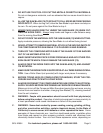
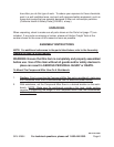
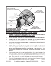
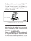
For illustration purposes, the saw is
shown in upright position. Saw should
be locked down during installation.
UPPER SCREW (#39)
FRAME
(#50)
MOVEABLE BAR
(#40)
LOWER SCREW
(#39)
LOWER ROLLER (#31)
LOWER ROLLER SHEATH
(#33)
FIXED BAR
(#34)
LEFT SIDE
HEX SCREW (#45)
(TEMPORARILY LOOSEN)
RIGHT SIDE
HEX SCREW (#45)
(TEMPORARILY REMOVE)
MOVEABLE COVER
(#43)
BACK PLATE (#46)
FIGURE F
UPPER ROLLER SHEATH (#33)
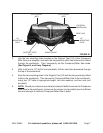
To Attach The Moveable Cover: (See Figure F, and Assy. Diagram.)
Caution: Prior to installing the Moveable Cover (43), make sure the Compound
Miter Saw is disconnected from its electrical power source.
Use the lock button Plastic Ball (51) to secure the saw arm in its lowered position.
Locate the two Hex Head Screws (45) on the frame. Use the wrench provided to
remove the front screw, and to loosen the rear screw a few turns.
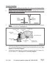
Use a cross head screwdriver (not included) to remove Screw (39) and Roller (33)
from the guard assembly.
Hold the blade guard assembly with the plastic cover down. With your other hand,
rotate the spring plate clockwise approximately one turn so there is tension on the
spring. Catch the rear slot in the plate under the head of rear Screw (45). Then
align the holes, and install the front Screw. Tighten both, and release the guard
carefully.
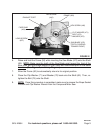
Check to make certain that the rear (forked) end of bar (40) is under the head of the
screw that guides it. Now release the lock button plastic ball (51), and raise the saw
arm. Align the forward slot in bar (40) with the threaded brass bushing in the spring
plate. Install screw (39) and roller (33) through the slot and into the bushing.
Check that all screws are tightened and for correct operation of the guard. It should
move downward to cover the blade as the saw is lowered.
1.
2.
3.
4.
5.
6.
7.