


Preparing for Drilling
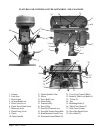
1. The Chuck (#9) is installed on the Spindle (#10) using a Morris Taper. This is a self-centering design.
2. Rotate the Chuck Fixing Lever (#8) counterclockwise to loosen the Spindle for vertical travel.
3. You can move the Spindle and Chuck vertically by operating the Chuck Feed Lever (#5).
4. Vertical movement of the Chuck and Spindle can be limited by setting the Chuck Travel Limit Screw
(#6). A Reference Scale (#7) indicates the relative travel of the Chuck.
5. For drilling blind holes (which do not pass through
the workpiece), set the Chuck Travel Limit Screw
(#6). To do so, first determine the desired depth.
Then adjust the Limit Screw so that the distance from
the tip of the drilling bit to the end of the gauge is
equal to the desired depth.
6. For drilling holes that pass through the workpiece,
loosen the Limit Screw so it does not interfere with
the vertical travel of the spindle.
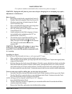
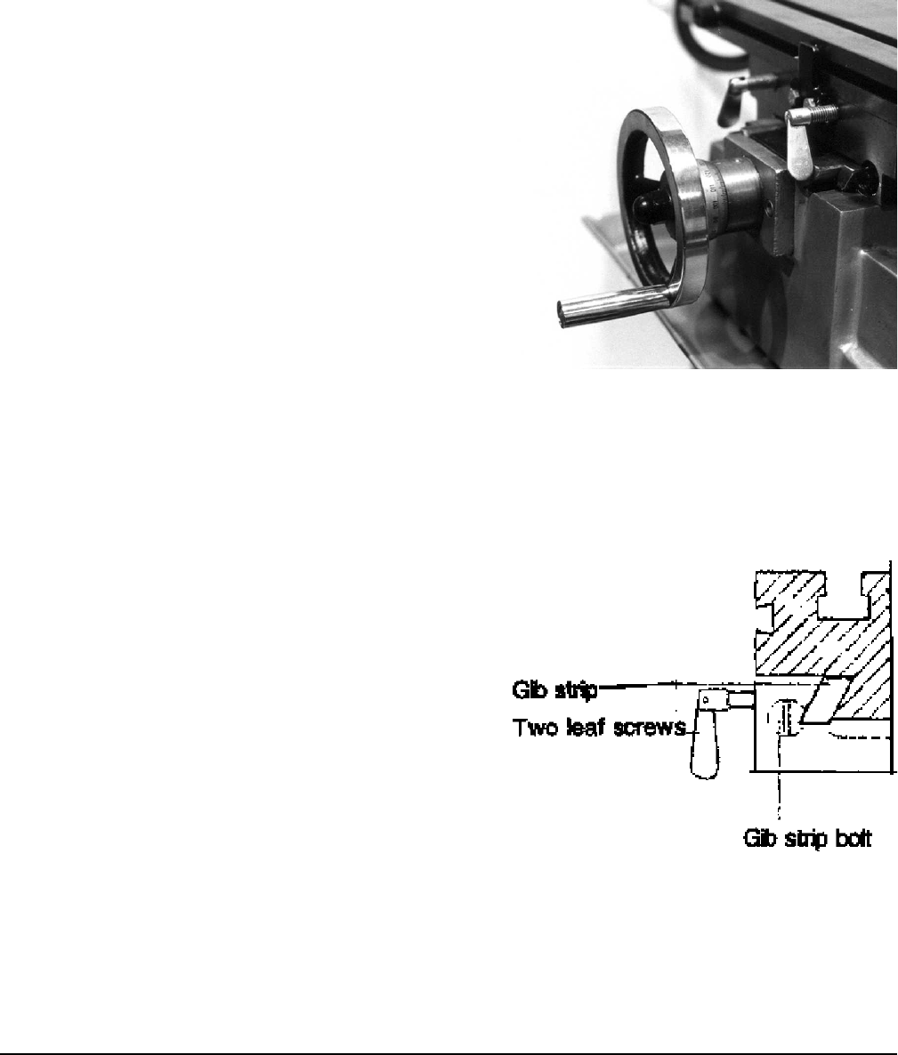
7. Be sure that the Vise or other fixture used to hold the
workpiece is properly attached to the table, and
aligned with the drill bit. Adjust alignment using the
vertical and cross table control wheels. The table can
be locked into position using the four Butterfly Lock
Bolts (#22) which are located under the Table on
the right side, and above the Cross-Feed Control Wheel.
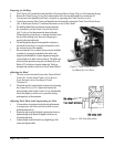
Adjusting the Head
1. To raise or lower the head, loosen the Vertical Head
Lock (#4). Use the Head Crank (#3) to raise or
lower the head on its Gear Strip (#2) and
Column (#1).
2. The head may be rotated on the column by loosening
the Control Lever (#19). Adjust the head to the
desired angle, then fix the Control Lever. Periodically
check the tightness of this lever, especially during
prolonged use of the machine.
Adjusting Table Slack and Compensating for Wear
1. Your machine is equipped with gib strip adjustment
to compensate for wear and excess slack on cross
and horizontal travel.
2. Rotate the gib strip bolt slightly counterclockwise to
tighten the gib strip. Rotate it slightly clockwise to
loosen the gib strip.
3. Adjust the gib strip bolt until very slight drag is felt
when moving the table.
Page 9 SKU # 42976
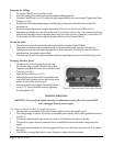
Figure 4. Gib StripAdjustment.
Figure 3. Table Control Wheel
and Butterfly Lock Bolts.