


Page 11SKU 43681
For technical questions, please call 1-800-444-3353.
THE THREADING DIAL
When the threads on the lead screw and on the workpiece
are not in an integer ratio, it is necessary to use the thread-
ing dial to control successive cuts. Determine this ratio by
dividing the desired TPI of the workpiece (for example 24 TPI)
by the thread pitch of the lead screw (8 TPI). This example
results in an integer ratio of 3:1. A desired thread pitch of 26
TPI (for example) on the workpiece would require use of the
threading dial.
When the threads on the workpiece are not in an in-
teger proportion to the threads on the lead screw, it is
necessary to operate the half nut intermittently. This is
controlled by using the threading dial.
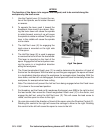
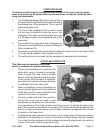
The Threading Dial (W) is located on the right side of
the apron.
The dial is marked with four numbered lines, 1, 2, 3,
and 4. Between each numbered line is an unnumbered
line. On the dial there is also a fixed reference line.
When the threading dial is engaged with the lead screw,
the dial will rotate.
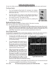
There is an instruction plate attached to the threading
dial explaining the use of the dial, depending on the
specific thread you are cutting.
For thread cutting, engage the half nut at the appropriate numbers shown on the thread-
ing dial. 1-4 means the half nut can be engaged at any of the numbered lines 1, 2, 3,
or 4. For successive cuts, only numbered lines must be used. 1-3 / 2-4 on the scale
means that the half nut can only be engaged on 1 and 3 or 2 and 4 for successive cuts.
For example, if you engage the half nut on “1” on the first cut, you can only engage it on
“1” or “3” on following cuts. If you engage it on “2” on the first cut, you can only engage
it on “2” and “4” on successive cuts.
1-8 means the half nut cannot be engaged on any lines, numbered or unnumbered.
If the half-nut is engaged throughout the initial cut, there is no need to use the thread-
ing dial. Simply disengage the half nut, back the tool to the starting point, reengage
the half nut and start over.
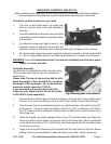
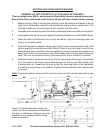
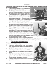
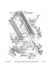
FOUR-POSITION TOOL REST
The four position tool rest can be used to hold up to
four tools. It is controlled by the three handwheels on
the Apron, the Saddle Handwheel (AA), the Cross Slide
Handwheel (Z) and the Compound Slide Handwheel
(N).
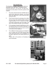
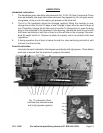
Tools are held in place on each side of the tool holder
by two or three of the bolts on that side. Tools must fit
into the tool groove.
When installing tools, check to see that the cutting
edge is properly aligned with the rotating direction of the workpiece.
The tool post can be rotated by loosening the Tool Post Clamping Lever (M), rotating
the tool post, and retightening the lever.
1.
2.
3.
4.
5.
6.
7.
8.
1.
2.
3.
Fig.10 Threading Dial.Fig.10 Threading Dial.
Fig.11 Tool Post.Fig.11 Tool Post.