


Page 9SKU 43681
For technical questions, please call 1-800-444-3353.
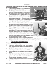
SPEED AND POWER CONTROLS
You can turn lathe on and off and control speed and direction from the main control panel.
The Power Switch
Turn the Emergency Stop Switch (C) clockwise; the Indicator
Light (D) will light up. The Spindle will not turn without operating
the Control Lever (V).
The Press Switch (A) is used to run the spindle temporarily to
allow the gears to engage when changing speed gears. When
you release the switch, the spindle will stop.
In an emergency, you can stop the machine by pressing the
Emergency Stop Control (C).
Speed and Direction Controls
Note: Do not change the settings of these controls if the motor is running.
Shut OFF the power before changing these settings.
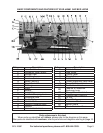
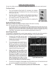
The Spindle Speed can be controlled by setting the Speed Control knobs (G) and (H).
Refer to the chart on the Headstock to the right of the knobs to determine the proper
setting for the desired spindle rotation speed. Eighteen speeds are possible from 72 to
1600 RPM. The direction may be controlled using Direction Control (F).
Quick Change Gearbox
The headstock is equipped with a quick change gearbox to control the rate of the spindle to
the lead screw and feed rod, when it is used to cut threads, or for turning or facing.
Controls (CC) and (EE) may be used
in combination to control the feed rate.
Please refer to the lead screw chart (HH)
for the desired setting.
The change gears may need to be re-
placed to achieve the correct setting.
Be sure the machine is turned off and is
unplugged from its power supply before
replacing the gears. Select the gears
required from the lead screw chart.
When the Exchange Lever (BB) is in the
middle position, the Lead Screw (118)
and Feeding Rod (107) are locked. When
Exchange Lever (BB) is to the right, the
Lead Screw (118) is running and the
machine can be used to turn the threads.
When Exchange Lever (BB) is to the
left, the Feeding Rod is running and the
machine can be used set for automatic feeding.
The half nut is engaged or disengaged using the Half Nut Lever (X). Note that the half
nut must be engaged for the lead screw to function properly.
1.
2.
3.
1.
2.
3.
4.
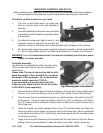
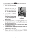
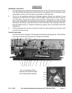
Fig.7 Power Switch.
SPEED AND POWER CONTROLS
You can turn your lathe on and off, and control its speed and direction from the main control panel.
The Power Switch
1. Push the power switch to turn the machine ON. Push the switch again to turn
the machine OFF.
2. The Indicator Light (D) will be on when the machine is running.
3. In an emergency, you can stop the machine by pressing the Emergency Stop
Control (C).
Fig.7 Power Switch.
Speed and Direction Controls
Note: Do not change the settings of these controls if the motor is running.
Shut OFF the power before changing these settings.
1. The Spindle Speed can be controlled by setting the Speed Control knobs (G) and (H). Refer
to the chart on the Headstock to the right of the knobs to determine the proper setting for the desired
spindle rotation speed. Nine speeds are possible from 64 to 1500 rpm. The direction may be
controlled using Direction Control (F).
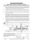
Quick Change Gearbox
The headstock is equipped with a quick change gearbox to control the rate of the spindle to the
lead screw and feed rod, when it is used to cut threads, or for turning or facing.
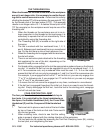
1. Controls (CC) and (EE) may be used in combination to
control the feed rate. Please refer to the lead screw chart
(HH) for the desired setting.
2. The change gears may need to be replaced in order to
achieve the correct setting. Be sure the machine is turned
off and is unplugged from its power supply before
attempting to replace the gears. Select the gears required
from the lead screw chart.
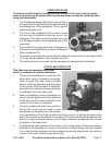
3. The Exchange Lever (BB) is used to activate and control
the direction of rotation. When the lever is in the middle
position, the lead screw is parked. When the lever is to
the right, the lead screw is running, and the machine can
be used to turn threads. When the lever is to the left, the
lead screw is reversed, and the machine may be used for.
internal or external machining or face cutting.
Fig.8 Lead Screw Chart.
4. The half nut is engaged or disengaged using the Half Nut Lever
(X). Note that the half nut must be engaged for the lead screw to function properly.
Page 9 SKU # 43681
Fig.7 Power Switch.
SPEED AND POWER CONTROLS
You can turn your lathe on and off, and control its speed and direction from the main control panel.
The Power Switch
1. Push the power switch to turn the machine ON. Push the switch again to turn
the machine OFF.
2. The Indicator Light (D) will be on when the machine is running.
3. In an emergency, you can stop the machine by pressing the Emergency Stop
Control (C).
Fig.7 Power Switch.
Speed and Direction Controls
Note: Do not change the settings of these controls if the motor is running.
Shut OFF the power before changing these settings.
1. The Spindle Speed can be controlled by setting the Speed Control knobs (G) and (H). Refer
to the chart on the Headstock to the right of the knobs to determine the proper setting for the desired
spindle rotation speed. Nine speeds are possible from 64 to 1500 rpm. The direction may be
controlled using Direction Control (F).
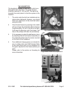
Quick Change Gearbox
The headstock is equipped with a quick change gearbox to control the rate of the spindle to the
lead screw and feed rod, when it is used to cut threads, or for turning or facing.
1. Controls (CC) and (EE) may be used in combination to
control the feed rate. Please refer to the lead screw chart
(HH) for the desired setting.
2. The change gears may need to be replaced in order to
achieve the correct setting. Be sure the machine is turned
off and is unplugged from its power supply before
attempting to replace the gears. Select the gears required
from the lead screw chart.
3. The Exchange Lever (BB) is used to activate and control
the direction of rotation. When the lever is in the middle
position, the lead screw is parked. When the lever is to
the right, the lead screw is running, and the machine can
be used to turn threads. When the lever is to the left, the
lead screw is reversed, and the machine may be used for.
internal or external machining or face cutting.
Fig.8 Lead Screw Chart.
4. The half nut is engaged or disengaged using the Half Nut Lever
(X). Note that the half nut must be engaged for the lead screw to function properly.
Page 9 SKU # 43681
Fig.8 Lead Screw Chart.
SPEED AND POWER CONTROLS
You can turn your lathe on and off, and control its speed and direction from the main control panel.
The Power Switch
1. Push the power switch to turn the machine ON. Push the switch again to turn
the machine OFF.
2. The Indicator Light (D) will be on when the machine is running.
3. In an emergency, you can stop the machine by pressing the Emergency Stop
Control (C).
Fig.7 Power Switch.
Speed and Direction Controls
Note: Do not change the settings of these controls if the motor is running.
Shut OFF the power before changing these settings.
1. The Spindle Speed can be controlled by setting the Speed Control knobs (G) and (H). Refer
to the chart on the Headstock to the right of the knobs to determine the proper setting for the desired
spindle rotation speed. Nine speeds are possible from 64 to 1500 rpm. The direction may be
controlled using Direction Control (F).
Quick Change Gearbox
The headstock is equipped with a quick change gearbox to control the rate of the spindle to the
lead screw and feed rod, when it is used to cut threads, or for turning or facing.
1. Controls (CC) and (EE) may be used in combination to
control the feed rate. Please refer to the lead screw chart
(HH) for the desired setting.
2. The change gears may need to be replaced in order to
achieve the correct setting. Be sure the machine is turned
off and is unplugged from its power supply before
attempting to replace the gears. Select the gears required
from the lead screw chart.
3. The Exchange Lever (BB) is used to activate and control
the direction of rotation. When the lever is in the middle
position, the lead screw is parked. When the lever is to
the right, the lead screw is running, and the machine can
be used to turn threads. When the lever is to the left, the
lead screw is reversed, and the machine may be used for.
internal or external machining or face cutting.
Fig.8 Lead Screw Chart.
4. The half nut is engaged or disengaged using the Half Nut Lever
(X). Note that the half nut must be engaged for the lead screw to function properly.
Page 9 SKU # 43681