


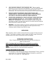
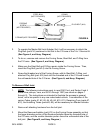

STEEL BALL
(NOT PROVIDED)
O-RING
(NOT PROVIDED)
FORCING
SCREW
(NOT PROVIDED)
PLUG BOLT (#14)
C-FRAME (NOT PROVIDED)
FIGURE A
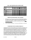
2. To operate the Master Ball Joint Adapter Set, it will be necessary to attach the
Plug Bolt (part #14) contained in this Set to the C-Frame of the 3-In-1 Service Kit.
(See Figure A, and Assy. Diagram.)
3. To do so, unscrew and remove the Forcing Screw, Steel Ball, and O-Ring from
the C-Frame. (See Figure A, and Assy. Diagram.)
4. Make sure the Steel Ball and O-Ring remain inside the Forcing Screw. Then,
insert the Plug Bolt (part #14) into the Forcing Screw.
5. Screw the threaded end of the Forcing Screw, with its Steel Ball, O-Ring, and
attached Plug Bolt (part #14) back into the threaded end of the C-Frame toward
the unthreaded hole of the C-Frame. (See Figure A, and Assy. Diagram.)
To Remove A Ball Joint:
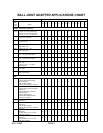
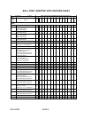
1. NOTE: The following instructions apply to most GM, Ford, and Dodge 2 and 4
wheel drive pickups, vans, and SUV’s through 1997 (see charts on pages 7
through 9). The instructions are intended to illustrate the process in general
terms, not to be specific to any one make/model vehicle. A combination of Re-
ceiving Tubes (parts #1, #2, #3, #4, #5, #6, #10, #11), Receiving Cups (parts #7,
#12), and Installing Tubes (parts #8, #9), will be necessary for different vehicles.
2. Remove all attaching hardware from the ball joint.
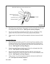
3. Mount the Remover/Installer (part #13) on the Forcing Screw assembly so that
the larger diameter portion of the Remover/Installer faces the threaded hole of
the C-Frame, and the smaller diameter portion faces the unthreaded side of the
ball joint. (See Figure B, and Assy. Diagram.)
SKU 46389 PAGE 5