


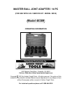
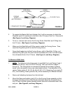
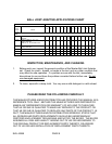

RECEIVER TUBE (#1, #2, #3, #4, #5, #6, #10, #11)
REMOVER/INSTALLER
(#13)
PLUG BOLT (#14)
FORCING SCREW
C-FRAME
FIGURE B
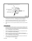
4. Mount the proper size Receiver Tube (parts #1, #2, #3, #4, #5, #6, #10, #11) over
the threaded side of the ball joint. (See Figure B, and Assy. Diagram.)
5. Align the mounted Remover/Installer (part #13), ball joint, and Reciever Tube
(parts #1, #2, #3, #4, #5, #6, #10, #11) to allow removal of the ball joint.
6. Using a wrench, turn the Forcing Screw assembly clockwise to remove the ball
joint.
To Install A Ball Joint:
1. Mount the Remover/Installer (part #13) on the Forcing Screw assembly so that
the larger diameter portion of the Remover/Installer faces the threaded hole of
the C-Frame, and the smaller diameter portion faces the unthreaded side of the
ball joint. (See Figure B, and Assy. Diagram.)
2. Place the mounted Remover/Installer (part #13) on the unthreaded side of the
ball joint. (See Figure B, and Assy. Diagram.)
3. Align the mounted Remover/Installer (part #13), ball joint, and proper size
Reciever Tube (parts #1, #2, #3, #4, #5, #6, #10, #11) to allow installation of the
ball joint. (See Figure B, and Assy. Diagram.)
4. Using a wrench, turn the Forcing Screw assembly clockwise to install the ball
joint. (See Figure B, and Assy. Diagram.)
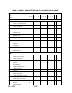
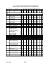
SKU 46389 PAGE 6