


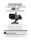

Page 6SKU 47404 For technical questions, please call 1-800-444-3353.
ASSEMBLY INSTRUCTIONS
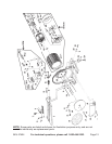
NOTE: For additional references to the parts listed below, refer to the Assembly
Diagram on page 12.
To Assemble The Disc Sander:
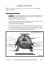
1. CAUTION: Prior to performing this procedure, make sure the Safety Switch (part
#32) of the Disc Sander is in its “OFF” position and the Power Cord/Plug (part
#34) is unplugged from its electrical outlet.
(See Figures C, D, and Assy. Diagram.)
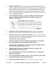
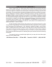
2. Assembly of the Disc Sander requires the attachment of one Knob Bolt (part #11)
on the front end and back end of the Work Table (part #7).
(See Figure B, and Assy. Diagram.)
3. Insert one Knob Bolt (part #11) onto each of the two Table Lock Assemblies (part
#10). Insert one Spring (part #12) into each of the two Knob Bolts. Then, screw
one Spring Adjusting Screw (part #13) into each of the two Knob Bolts to secure
the Knob Bolts in place. (See Figure B, and Assy. Diagram.)
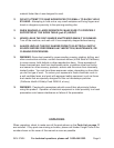
KNOB (#1)
MITER GAUGE (#3)
KNOB BOLT (#11)
SPRING (#12)
SPRING ADJUSTING
SCREW (#13)
10” PRESSURE SENSITIVE
ADHESIVE SANDING DISC (#14)
DISC (#15)
WORK TABLE (#7)
KNOB BOLT (#11)
SPRING (#12)
SPRING ADJUSTING
SCREW (#13)
BASE (#23)
DUST COVER (#18)
FIGURE B
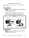
ALWAYS FEED WORKPIECE INTO AND AGAINST
THE ROTATION DIRECTION OF THE SANDING DISC.
WORKPIECE
ROTATION DIRECTION