


Page 7SKU 47404 For technical questions, please call 1-800-444-3353.
MACHINE ADJUSTMENT INSTRUCTIONS
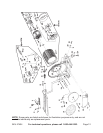
NOTE: For additional references to the parts listed below, refer to the Assembly
Diagram on page 12.
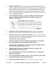
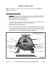
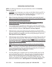
To Adjust The Table Angle:
1. CAUTION: Prior to performing this procedure, make sure the Safety Switch (part
#32) of the Disc Sander is in its “OFF” position and the Power Cord/Plug (part
#34) is unplugged from its electrical outlet.
(See Figures C, D, and Assy. Diagram.)
2. The Work Table (part #7) may be angled downward from 0 to 45 degrees. To
do so, slightly loosen the two Knob Bolts (part #11). Move the Work Table
downward until the Angle Scale indicates the desired angle. Then, rmly
retighten the two Knob Bolts. (See Figures B, C, and Assy. Diagram.)
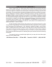
SAFETY SWITCH (#32)
SAFETY SWITCH (#32)
DISC (#15)
DISC (#15)
WORK TABLE (#7)
ANGLE SCALE
KNOB BOLT (#11)
KNOB BOLT (#11)
ANGLE SCALE WORK TABLE (#7)
FIGURE C
FRONT VIEW
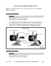
To Adjust The Miter Angle:
1. CAUTION: Prior to performing this procedure, make sure the Safety Switch (part
#32) of the Disc Sander is in its “OFF” position and the Power Cord/Plug (part
#34) is unplugged from its electrical outlet.
(See Figures C, D, and Assy. Diagram.)