


Page 10SKU 66787 For technical questions, please call 1-800-444-3353.
WELDER FEATURES
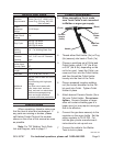
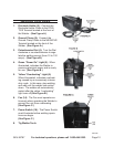
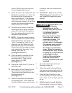
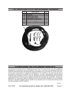
Electrode Holder (8):1. Connect the
Electrode Holder Cable to the POSI-
TIVE Terminal located at the front of
the Welder. (See Figure A.)
Ground Clamp (9): 2. Connect the
Ground Clamp Cable to the NEGATIVE
Terminal located on the front of the
Welder. (See Figure A.)
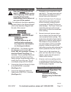
Potentiometer Dial (4): 3. Turn the Dial
clockwise or counterclockwise to regu-
late the welding current (from 10 to 130
amps). (See Figure B.)
Green “Power On” Light (5): 4. When
illuminated, indicates the Welder is
receiving electrical power and is ready
for use. (See Figure B.)
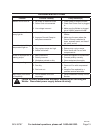
Yellow “Overheating” Light (5): 5.
When illuminated, indicates overheat-
ing caused by an excessively intense
duty cycle. In this case, stop welding
and wait until the welder has cooled
down. The welder will automatically
restart after the yellow “overheating”
light turns off.(See Figure B.)
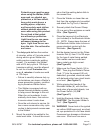
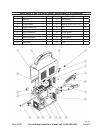
Fan (14): 6. The Fan must operate con-
tinuously when operating the Welder to
prevent the unit from overheating.
(See Figure C.)
Power Switch (16): 7. The Power Switch
must illuminate before welding opera-
tions can begin.
(See Figure C.)
Tig Welder Torch8.
REV 09h