


Page 12SKU 66787 For technical questions, please call 1-800-444-3353.
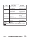
Protective gear must be worn
when using the Welder; ANSI-
approved, arc shaded, eye
protection, a full face shield,
heavy duty work gloves, a
welding apron, respirator,
and heavy-duty work clothes
without pockets should be
worn when using this product.
Do not look at the ignited
arc without eye protection.
Light from the arc can cause
permanent damage to the
eyes. Light from the arc can
burn the skin. Do not breathe
arc fumes.
The 1. duty cycle denes the number
of minutes, within a 10 minute period,
during which a given Welder can
safely produce a particular welding
current. For example, this Welder,
with a 40% duty cycle at 130 Amps
(maximum setting), must be allowed
to rest for at least 6 minutes after
every 4 minutes of continuous weld
at 130 Amps.
Failure to carefully observe duty cy-•
cle limitations can stress a Welder’s
power generation system, contribut-
ing to premature Welder failure.
This Welder is equipped with an •
internal thermal protection system
to help prevent damage to the unit.
When the unit overheats; it auto-
matically shuts down, then returns
to service when it cools down.
Once the unit returns to service, fol-•
low a more conservative duty cycle
routine to help prevent excess wear
to the Welder.
Mount the metal to be welded to the 2.
metal work table. It should be mount-
ed so that the welding debris falls to
the cement oor.
Place the Welder no closer than six 3.
feet from the workpiece to be welded
and attach the Tig Torch, if desired.
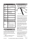
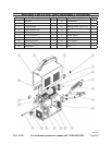
Securely attach the Ground Clamp 4.
(9) to a part of the workpiece or metal
table. (See Figure A.)
Place the bare end of an Electrode 5.
(not included) in the Electrode Holder
(8). NOTE: Always keep the jaws of
the Electrode Holder clean to ensure
proper electrical contact with the
Electrode. (See Figure A.)
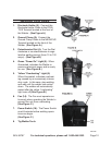
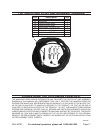
Set the desired current on the Poten-6.
tiometer Dial (4) from 10 to130 amps
for the type of metal being welded.
Thin metals use low current and
heavy metals use high current.
(See Figure B.)
Make sure the Power Switch (16) is 7.
OFF. Then plug the Welder’s Power
Cord (17) into the nearest 240 volt,
dedicated, grounded, electrical outlet
with delayed action type circuit break-
er or fuse. (See Figure C.)
While gripping the Handle of the 8.
Electrode Holder (8), with the Elec-
trode clear of grounded objects, turn
the Power Switch (16) ON.
(See Figure C.)
Hold the Electrode Holder (8) rmly. 9.
CAUTION! The Electrode Holder is
“live”. (See Figure A.)
WARNING! 10. Never look at the ignited
arc without ANSI-approved, arc shad-
ed, eye protection in a full face shield.
Permanent eye damage or blindness
can occur. Skin burns can occur.
REV 09h