


SKU 95082 For technical questions, please call 1-800-444-3353. Page 8
SPECIFICATIONS
Electrical Requirements 120 V~ / 60 Hz / 11.8 A
Motor (Cutter head)
Speed
2-1/2 HP, 18,800 cuts
per minute
Maximum Cutting Depth 3/32”
Stock Capacity 4-1/2” x 12” lumber
Feed Speed 20 Feet per Minute
Included
Accessories
1 Hex Wrench (4mm)
2 Magnets, 1 Dust Bag,
UNPACKING
When unpacking, check to make sure
item is intact and undamaged. If any parts
are missing or broken, please call Harbor
Freight Tools at the number shown on the
cover of this manual as soon as possible.
INSTRUCTIONS FOR
PUTTING INTO USE
Read the ENTIRE IMPORTANT
SAFETY INFORMATION
section at the beginning of this
manual including all text under
subheadings therein before set
up or use of this product.
TO PREVENT
SERIOUS INJURY
FROM ACCIDENTAL
OPERATION: Turn the Power
Switch of the tool to its “OFF”
position and unplug the tool
from its electrical outlet
before assembling or making
any adjustments to the tool.
Note: For additional information regarding
the parts listed in the following pages,
refer to the Assembly Diagram near
the end of this manual.
Assembly
NOTE: 1. This should always be mount-
ed to a workbench before use.
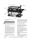
Select an area with enough room to 1.
Select a workbench to mount the
Planer. Place the Planer on a work-
bench able to support the weight of
the Planer and the wood stock being
planed. The orientation of the Planer
should enable the easy entry and exit
of long pieces of wood stock.
Using a pencil, mark through the 2.
mounting holes of the Planer, onto
the workbench. Slide the Planer
aside and drill four 3/8 inch mounting
holes into the workbench.
Before drill-
ing, verify that there are no utility
wires or other obstructions under
the workbench.
Slide the Planer back over the mount-3.
ing holes in the workbench, and se-
cure the Planer to the workbench with
bolts, washers, spring washers and
nuts (not included). Securely tighten.
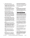
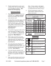
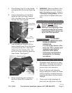
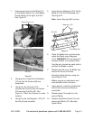
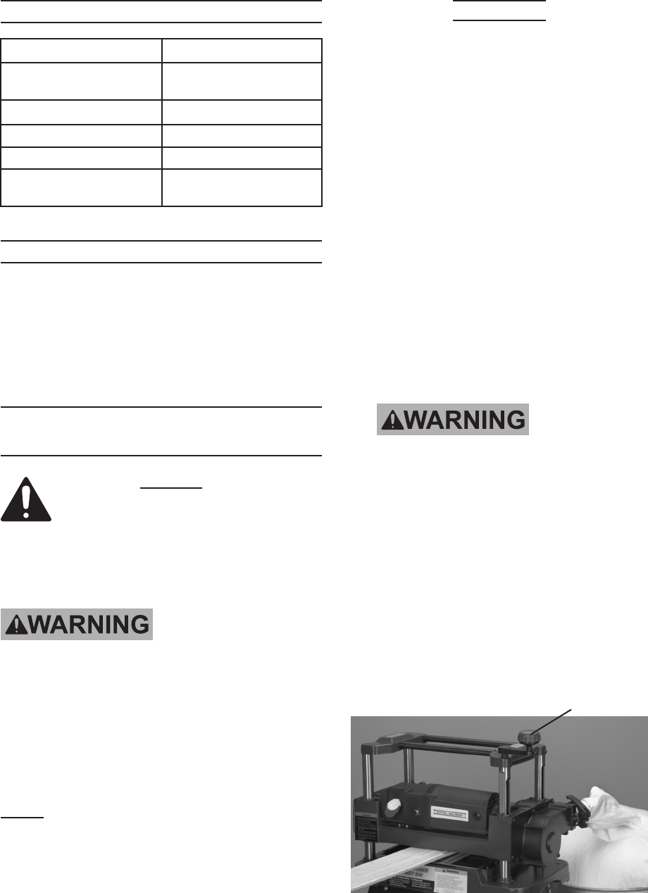
Mount the height (thickness) adjust-4.
ment Handle (10) to the Right Cap
(11). See Figure A.
Figure A
Crank
Handle (10)
Rev 10d