


Page 12SKU 98676 For technical questions, please call 1-800-444-3353.
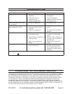
Gib: An adjustable length of steel or
brass with a diamond shaped cross-
section that engages one side of the
dovetail slide. Used to adjust the
dovetail for optimum tightness and to
compensate for wear.
Headstock: The main casting
mounted on the left end of the bed
where the spindle is mounted. Hous-
es the spindle gears.
Morse Taper (MT): A taper of spe-
cic dimensions used to mate match-
ing male and female parts together
tightly. The spindle has a #2 Morse
Taper (MT-2) and the tailstock has a
#2 Morse Taper (MT-2).
Saddle: An “H” shaped casting that
rides along the ways. A main compo-
nent of the carriage.
Spindle: Main rotating shaft on
which the chuck is mounted. It pass-
es through the headstock.
Spindle Through-hole: A dimen-
sion indicating the minimum diameter
of the hole that passes through the
spindle. A workpiece with a diameter
smaller than this can pass through
the spindle to work on longer pieces.
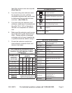
Swing: A dimension representing
the largest diameter workpiece that a
lathe can rotate. The 14” x 43” Lathe
has a 14-5/8” swing, meaning that the
maximum size workpiece that can ro-
tate without hitting the bed is 14-5/8”
in diameter.
Tailstock: Assembly that slides
along the ways and can be locked in
place. Used to hold long workpieces
in place or to mount a drill chuck.
Tailstock Handwheel: Moves the
tailstock in and out. Has a tapered
internal bore to accept a #2 Morse
Taper shank.
Tool Post: A device mounted on the
compound that holds the cutting tool.
Turning: A lathe operation that re-
moves wood from the outside diam-
eter of the workpiece.
Ways: Surface along the top of the
bed on which the saddle rides. The
ways are aligned with the centerline
of the lathe.
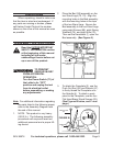
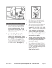
ADJUSTMENTS
The Headstock (1) has 1. ve preset
positions:
0°• setting for all spindle turning ap-
plications.
60°, 90°, and 120°• for use when
making Faceplate turnings.
180°• for use when making Face-
plate turnings when using the Ex-
tension Bed and Toolrest.
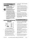
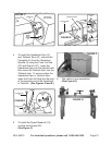
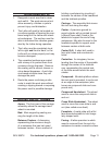
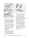
To set the Headstock (1) at the de-2.
sired position, turn the Angular Set-
ting Assembly (45) until you have
completed at least one rotation.
Pull out the Eccentric Rod (25). Ro-3.
tate the entire Headstock (1) clock-
wise to the desired position. The
Headstock will be locked in position
when it “clicks” into one of the ve
preset settings. Then retighten the
Angular Setting Assembly (45).
(See Figure H.)