


Page 9SKU 98676 For technical questions, please call 1-800-444-3353.
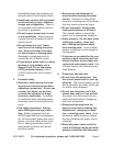
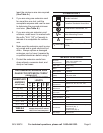
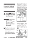
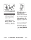
FIGURE B
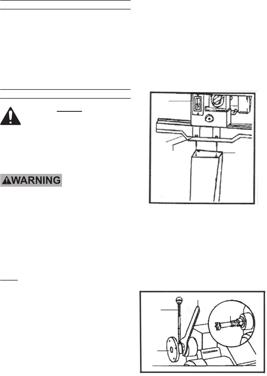
FACEPLATE
(2)
WRENCH
(47)
PUSH OUT ROD
(22)
HEADSTOCK
SPUR
(3)
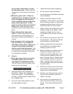
UNPACKING
When unpacking, check to make sure
that the item is intact and undamaged. If
any parts are missing or broken, please
call Harbor Freight Tools at the number
shown on the cover of this manual as soon
as possible.
ASSEMBLY INSTRUCTIONS
Read the ENTIRE IMPORTANT
SAFETY INFORMATION section
at the beginning of this manual
including all text under
subheadings therein before set
up or use of this product.
TO PREVENT
SERIOUS INJURY
FROM ACCIDENTAL
OPERATION:
Turn the Power Switch (71) of
the Lathe to its “OFF”
position and unplug the tool
from its electrical outlet
before assembling or making
any adjustments.
Note: For additional information regarding
the parts listed in the following pages,
refer to the Assembly Diagram near
the end of this manual.
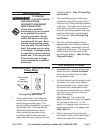
NOTE: This product is very heavy 1.
(282.2 lb.). The following assembly
procedures will require at least two
additional personnel and a proper lift-
ing device.
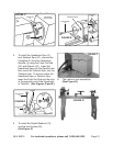
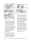
Place the Bed (38) assembly on the 2.
two Stand Legs (74, 78). Align the
mounting holes in the Bed assembly
with the mounting holes at the tops
of the two Stand Legs. Secure the
Bed assembly to the two Stand Legs
using eight Screws (69), eight Spring
Washers (75), and eight Nuts (33).
Then set the Headstock (1) upon the
Bed assembly. (See Figure A.)
FIGURE A
HEADSTOCK
(1)
BED
(38)
SCREWS (69)
SPRING WASHERS (75)
NUTS (33)
STAND LEGS
(74, 78)
To attach the Faceplate (2), use the 3.
Push Out Rod (22) and Wrench (47)
to rmly thread the Faceplate onto
the Spindle (4). To attach a work-
piece to the Faceplate, use the four
Flat Head Brass Wood Screws (83).
(See Figures B below, and C next
page.)