H.E.R.O. INDUSTRIES 1150GSD MANUAL - “B” VERSION
14
TROUBLESHOOTING
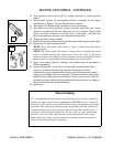
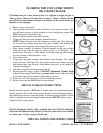
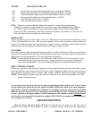
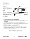
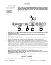
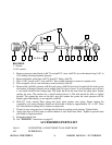
The backward movement of the piston, creates a vacuum in the hydraulic system. This causes the
hydraulic outgo valve to close and the hydraulic intake valve to open (fig# 1). Opening of the hydraulic
intake valve allows a new supply of hydraulic oil to enter the system, replacing the oil which was used on the
forward stroke. Once again a corresponding re-action is taking place in the paint pump. The hydrapulse
membrane is being pulled backward by the hydrapulse membrane spring, (ref# 56). The backward
hydrapulse membrane movement causes a vacuum in the paint pump. This vacuum causes the intake valve
to open, allowing a new supply of paint to enter. The corresponding paint outgo valve is drawn closed by the
vacuum created by the hydrapulse membrane.
These operations are repeated at a rate of 750 times a minute. These continuously repeated actions draw
paint into the pump, pressurize it, and then deliver it to the gun. The failure, of any one valve, to operate
correctly will effect the overall equipment performance. Each of the five valves mentioned earlier, have an
important function and will effect the overall performance of the unit if not performing correctly.
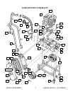
HYDRAULIC INTAKE VALVE (REF# 66, PART # 4-30)
The hydraulic intake valve, is a small vacuum valve which controls the hydraulic oil entering the
hydraulic pump/cylinder area. Once the oil has past through the valve it is prevented from returning. The
valve is commonly called a “one way check valve”. Valve failure will result in the hydraulic pump being
unable to build pressure, and the hydrapulse membrane will stop moving. Spray pressure will cease.
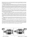
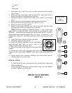
HYDRAULIC OUTGO VALVE (REF# 74, PART# 4-27C)
The hydraulic outgo valve, better known as the "pressure control valve", is used to control the units
operating pressure. The valve is fully adjustable from 0 psi. to 3000 psi. By turning the pressure control valve
knob (ref# 75) clockwise the pressure is increased. The hydraulic pump continues to build at all times and
must have a means of releasing this pressure. Pressure applied to the P.C. ball, (ref# 88) will keep it lodged in
the P.C. seat (ref# 87) until the internal hydraulic oil pressure is sufficient to cause it to open. The point at
which the oil is released is equal to the level set by the control knob. As components within the pressure
control valve wear, the valve looses its ability to maintain or reach the required pressures (see "low static
pressure").
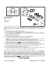
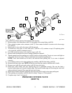
PAINT INTAKE VALVE ASSEMBLY (REF# 11-18)
The paint intake valve is made up of eleven items, endcap (ref# 11), washer (ref# 12), seat (ref# 13)
intake ball (ref# 14), spring (ref# 15), o-ring (ref# 16), ball guide (ref# 17), and ball stop (ref# 18). The intake
valve controls the incoming flow of spray materials and is responsible for keeping them from returning to the
source. The ball must be able to create a complete seal on the seat, otherwise pressure will be lost. A worn
intake valve will permit correct static pressure, but supply lower spray pressure. A worn intake ball will
become smaller in diameter and loose its ability to seal at the seat. A worn seat will develop a large step in
the area where contact with the ball is made. This can cause the intake ball to distort in shape making the ball
egg shaped. If the valve assembly becomes warm to the touch, this may be a sign of a loose or worn seat
caused by wear or improper compression caused by a worn intake washer (ref# 12). The intake washer (ref#
12), acts as a compression washer insuring the seat (ref# 13) remains pressed into the endcap (ref# 11). The
seat must remain firmly pressed into the endcap at all times, through the correct assembly of parts listed, and
the correct bolt torque. Replace the intake washer (ref# 12) each time the endcap is removed. See page 23 for
details.
TROUBLESHOOTING