H.E.R.O. INDUSTRIES 1150GSD MANUAL - “B” VERSION
16
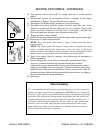
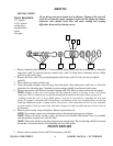
PRESSURE TEST
To verify the operation of an airless sprayer, use of pressure gauge is required. A pressure gauge (min. 3000
psi) installed at the gun, using a new .021 tip, and not less than 50 feet of H.E.R.O. airless spray hose is
needed. If you do not have access to these items, your local H.E.R.O. authorized service center will be able
to perform this test. Your model 1150GSD is manufactured to perform at;
2650 psi -- Static pressure, with lock ring (ref# 77) on pressure control valve (ref# 74).
1950 psi -- Pressure drop, when gun trigger is squeezed.
2250 psi -- Spraying pressure, after recovery time.
If your unit is unable to perform to the above pressure levels consult the troubleshooting guide for the
required repair procedure.
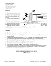
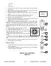
HYDRAPULSE MEMBRANE TEST
If your unit is disabled and you are unable to perform a pressure test, use the following procedures for
determining the area to repair. This test will divide the two halves of the equipment (hydraulic from paint)
and make identification of your solution easier to obtain. This test is commonly referred to as the
"Hydrapulse membrane Test"
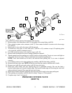
The solution to almost all problems can be found in the paint side valves, due to the increased wear from
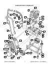
contact with the abrasive paint/spray materials. Intake valve (ref# 11-18), Outgo valve (ref#26), and Prime
valve (ref# 36) make up the three paint valves. Refer to pages where exploded views of these valves are
shown. To eliminate the hydraulic side of the pump (piston side of hydrapulse membrane) as a source of
problems;
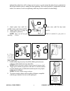
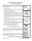
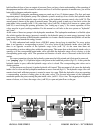
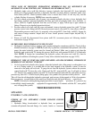
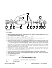
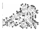
1. Remove the intake valve end cap (ref# 11) by removing the four cap screws (ref# 9 ). The intake valve
assembly, (ref# 11- 18), will generally come off as an entire assembly, requiring no f u r t h e r
dismantling. If the ball guide (ref# 17) and ball stop (ref# 18),
remain in the paint head, they can be pried free w i t h a
screwdriver.
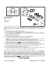
2. Start unit.
3. Increase the pressure by turning the pressure control knob
(ref# 71) clockwise to full pressure.
4. Put pressure on the center of the exposed hydrapulse
membrane with the handle of a screwdriver or other blunt
object.
NOTE: The hydrapulse membrane is located between the
paint head (ref# 21) and the hydraulic head (ref# 59)
5. If you are UNABLE to stop or alter the hydrapulse
membrane's movement, then the hydraulic side is operating
properly. The problem is located in the “Paint” pump. See
troubleshooting guide for additional information.
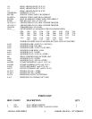
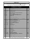
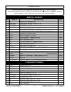
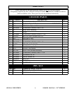
TROUBLESHOOTING
SITUATION
POSSIBLE CAUSE (REMEDY)
11
9
59 21