H.E.R.O. INDUSTRIES Model 3000 Owner’s Manual
14
TROUBLESHOOTING
Hydraulic Energy Regulated Output (H.E.R.O.) is more than just our name, it is the bases for the
operation of the pump. It is the regulation or control, of hydraulic energy, which allows the equipment to
build and then deliver or have an output of pressure. Once you have a basic understanding of the operation of
the equipment and the effect created in one area and how it will effect operation in another area, you will be
better able to diagnose and make repairs.
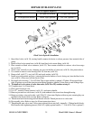
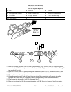
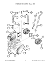
All H.E.R.O. diaphragm pumps are made up of two (2) distinct pumps. The first, and most important
pump is the hydraulic pump. The hydraulic system is made up of two valves, the hydraulic intake valve (ref#
62) and the hydraulic outgo valve, known as the hydraulic pressure control valve (ref# 73). The second pump
is known as the paint or material pump. The paint system is made up of two basic valves, the paint intake
valve assembly (ref# 11-15), paint outgo valve, (ref# 22). A third valve, known as a prime valve (ref# 34) is
used during the priming procedure, (see "setting up to spray"). For correct operation, all five valves must be
in good working condition. For this manual we will refer to the two systems as "hydraulic" and "paint".
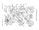
At the center of these two pumps is the diaphragm. The diaphragm is a flexible nylon disc which transfers
the energy (pressure) created by the hydraulic pump, to create energy (pressure) in the paint pump. The
function of the diaphragm is to create a barrier between the hydraulic oil and the spray material and transfer
the energy created.
To fully understand and trouble shoot a H.E.R.O. pump, always keep in mind that "for every action,
there is an opposite or corresponding re-action". For every action of the hydraulic intake valve (ref# 62),
there is an opposite re-action of the hydraulic outgo valve (ref# 73). At the same time there are
corresponding re-actions taking place within the paint pump. This means that as the hydraulic intake valve is
opening, so is the corresponding paint intake valve, and while the hydraulic outgo valve is closing, so is the
corresponding paint outgo valve. The operation and function of each valve is discussed at the end of this
section.
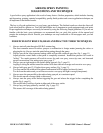
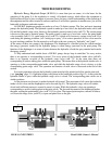
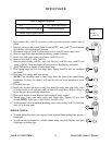
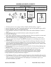
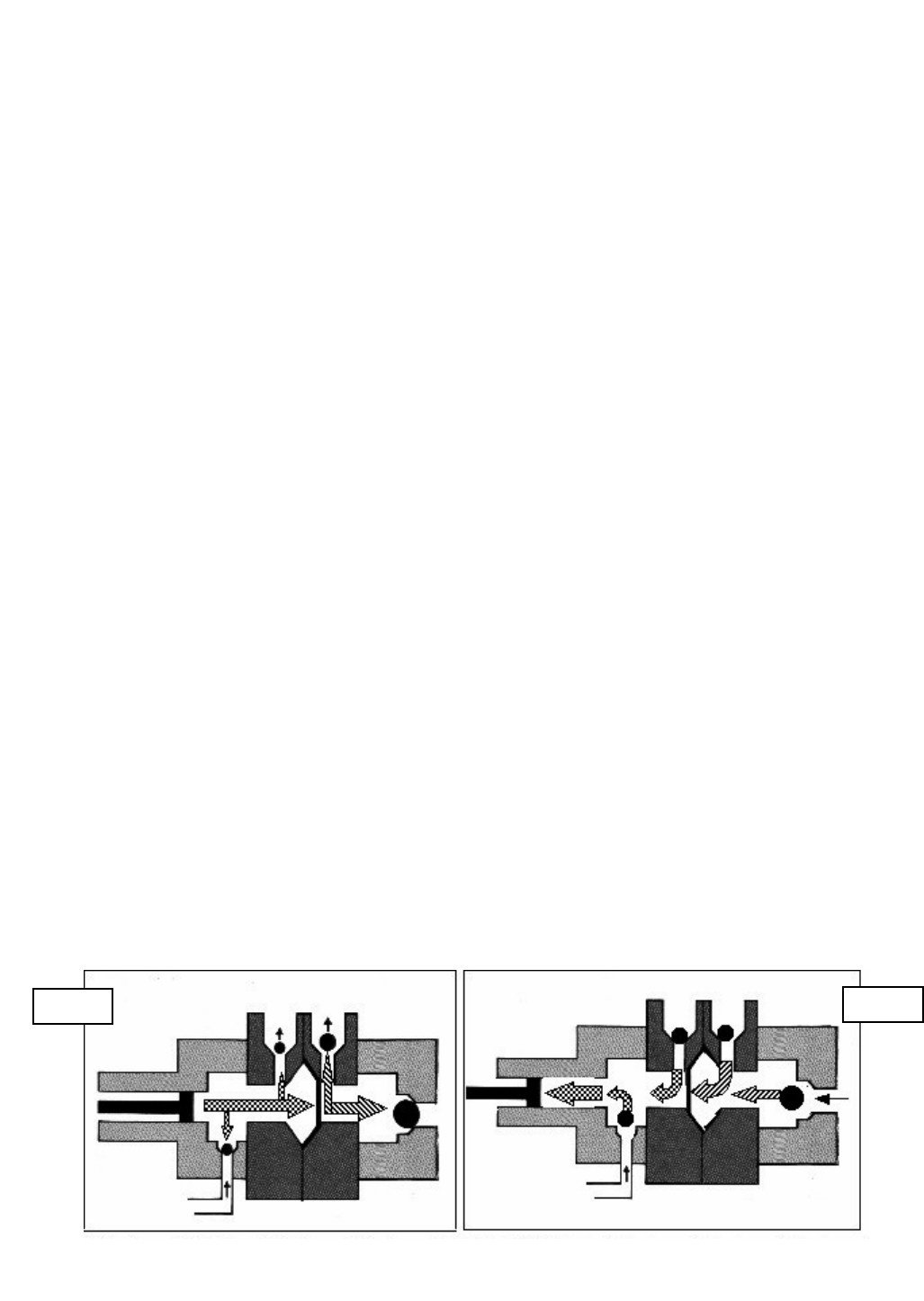
For correct operation to begin, the hydraulic system must be fully primed and all air must be removed
( see "purging" page 19 ). Operation begins with piston in the backward position (fig.# 2). At this point the
hydraulic intake is open, while the hydraulic outgo valve is closed. The corresponding paint valves are in
similar positions.
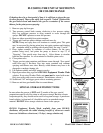
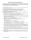
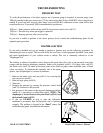
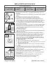
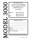
As the piston moves forward, it pushes hydraulic oil forward. This movement of oil causes the hydraulic
intake valve to close and the diaphragm to move forward (fig.# 1). The hydraulic outgo valve will remain
closed until sufficient pressure is created to cause it to open. While the hydraulic valves are operating a
corresponding re-action is taking place in the paint valves. The forward movement of the diaphragm pushes
the paint, causing the paint intake valve, (ref# 11-15) to close. The trapped paint requires a means of release,
so it forces the outgo valve, (ref# 22), to open and paint flows to the gun.
Fig. 1
Fig. 2