H.E.R.O. INDUSTRIES Model 3000 Owner’s Manual
19
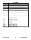
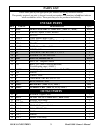
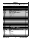
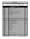
TROUBLESHOOTING
SITUATION
POSSIBLE CAUSE (REMEDY)
TOTAL LOSS OF PRESSURE, DIAPHRAGM HAS NO MOVEMENT OR MOVEMENT CAN BE
STOPPED...CONTINUED.
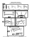
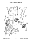
2. Air lock created on hydraulic side of pump. (air entering hydraulic side due to loose hydraulic feed
line fittings, (ref# 63), punctured hydraulic feed line, poor seal at hydraulic intake valve, (ref# 62), or
elbow, (ref# 61). Tighten hydraulic feed line, test for leaks, or apply Teflon tape or pipe sealant on
fittings. Purge air as per detailed instructions below).
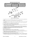
3. Pressure control valve ball (ref# 87) worn out/jammed. (remove hydraulic return line, (ref# 72), from
pressure control valve fitting, (ref# 81). Remove pressure control valve, (ref# 73), from elbow, (ref# 61).
Disassemble pressure control valve, by removing valve seat, (ref# 86), from body, (ref# 82). Inspect for
and remove foreign material. Inspect ball for wear. Install pressure control repair kit, (ref# 88), if
necessary).
4. Piston rod (ref# 93) disconnected from piston (ref# 91). (reconnect piston rod following detailed
instructions on page 28-29).
NO PRESSURE, BLUE HYDRAULIC FLUID IN PAINT
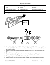
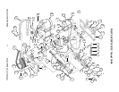
1. Diaphragm broken. (replace with complete diaphragm, (ref# 51). Closely follow detailed instructions on
page 26. NOTE; If, and only if, paint has contaminated the hydraulic side of the pump, the entire
hydraulic system must be cleaned and flushed. Make sure to remove and clean the hydraulic tank screen,
(ref# 66), during this process. Refill only with genuine H.E.R.O. LVO hydraulic fluid.
NOTE; If lacquer has contaminated the hydraulic system, the piston seal, (ref# 90), must be changed
in addition to flushing the system. Closely follow detailed instructions on page 28-29).
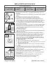
HYDRAULIC SIDE OF PUMP HAS BEEN REPAIRED AND REASSEMBLED, DIAPHRAGM NOT
MOVING "PURGING"
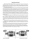
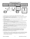
1. Air lock created on hydraulic side of pump. (when the hydraulic side of the pump is working there is no
air in it. During repairs it is possible that air has been trapped in the hydraulic system. It must be removed
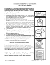
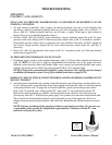
or the pump will not work. To purge the air from the hydraulic system; remove the pressure control
knob, (ref# 74), from the valve. Gently pull the P.C. stem, (ref# 77), out. It will pull out about 1/8".
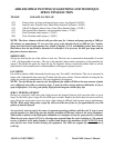
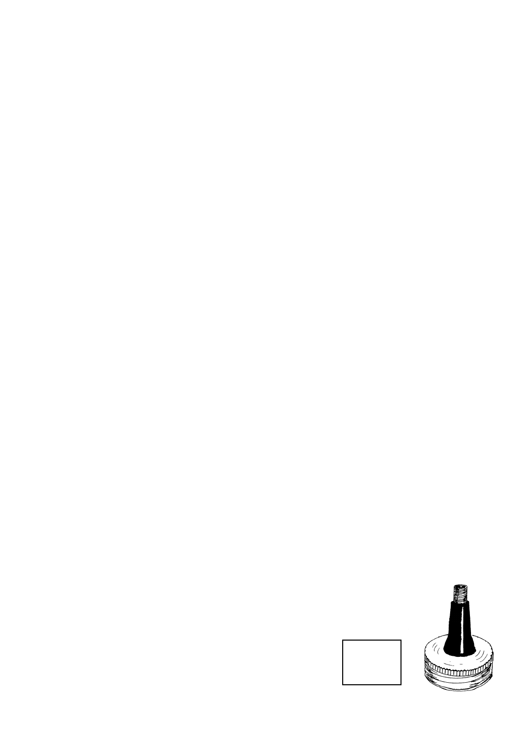
Remove the vented hydraulic cap, ref# 68), from the hydraulic tank, (ref# 65), and install accessory
pressure cap, item 4-45-3. With a bicycle pump, apply a few pounds of air pressure to the hydraulic tank.
This will force the oil through the hydraulic system and push out any of the trapped air. Wait a few
minutes. Remove pressure cap and replace with vented cap. Restart the unit and install pressure control
knob.
NOTE: Unit may be running during purging procedure to speed up the procedure. If a pressure cap
is unavailable, simply running the equipment for approximately 5-10 minutes with the P.C. stem
pulled out, will purge the system).
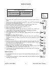
Accessory
Item
4-45-3