


12
English
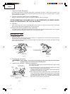
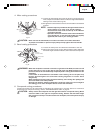
7. Check the Power Receptacle.
To prevent overheating, accidental stopping or intermittent operation, confirm that the power cord
plug fits properly in the electrical receptacle and does not fall out after it is inserted. Repair or replace
the receptacle if it is faulty.
8. Confirm the tool’s power cord is not damaged.
Repair or replace the power cord if an inspection indicates that it is damaged.
AFTER CONNECTING THE POWER PLUG TO AN APPROPRIATE AC POWER SOURCE,
CHECK THE OPERATION OF THE TOOL AS FOLLOWS:
9. Trial Run
After confirming that no one is standing behind, the power tool start and confirm that no operating
abnormalities exist before attempting a cutting operation.
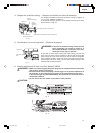
10. Inspect the rotating stability of the saw blade.
For precise cutting, rotate the saw blade and check for deflection to confirm that the blade is not noticeably
unstable; otherwise vibrations might occur and cause an accident.
BEFORE CUTTING
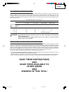
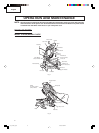
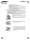
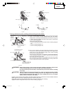
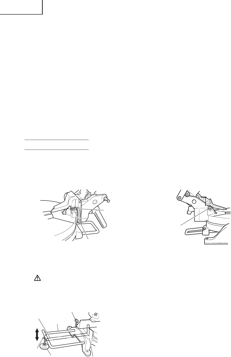
1. Oblique angle
Before the power tool is shipped from the factory, it is adjusted for 0°, left 45° bevel cutting angle with
the 8mm bolt (A) and the 8mm bolt (B).
When changing the adjustment, change the height of the 8mm bolt (A) or the 8mm bolt (B) by turning
them. (Fig. 8-a, Fig. 8-b)
Fig. 8-a Fig. 8-b
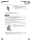
2. Securing the workpiece
WARNING: Always clamp or vise to secure the workpiece to the fence; otherwise the workpiece
might be thrust from the table and cause bodily harm.
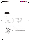
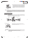
3. Installing the holders ... (Optional accessory)
The holders help keep longer workpieces stable and in place during
the cutting operation.
(1) As indicated in Fig. 9, use a steel square for aligning the upper
edge of the holders with the base surface.
Loosen the 6mm wing nut. Turn a height adjustment bolt 6mm,
and adjust the height of the holder.
(2) After adjustment, firmly tighten the wing nut and fasten the
holder with the 6mm wing bolt (optional accessory). If the length
of Height Adjustment Bolt 6mm is insufficient, spread a thin
plate beneath. Make sure the end of Height Adjustment Bolt
6mm does not protrude from the holder.
Fig. 9
8mm Bolt (A)
(Stopper for 0°)
Indicator
(For bevel scale)
8mm Bolt (B) (Stopper
for left 45° bevel angle)
6mm Wing Bolt
(Optional accessory)
Holder
(Optional
accessory)
Steel
Square
Base Surface
6mm Wing
Nut (Optional
accessory)
Height Adjustment
Bolt 6mm (Optional
accessory)
01e_c10fch_e.p65 1/21/04, 0:05 PM12