


15
English
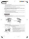
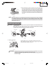
(3) After adjusting the position of the laser line, draw a right-angle
ink line on the workpiece and align the ink line with the laser
line. When aligning the ink line, slide the workpiece little by
little and secure it by vise at a position where the laser line
overlaps with the ink line. Work on the grooving again and check
the position of the laser line. If you wish to change the laser
line's position, make adjustments again following the steps from
(1) to (3).
Fig. 17
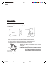
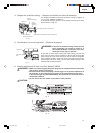
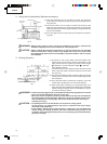
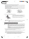
NOTE: Check and make sure on a periodic basis if the position of the laser line is in order. As regards
the checking method, draw a right-angle ink line on the workpiece with the height of about
1-1/2" (38mm) and the width of 3-1/2" (89mm), and check that the laser line is in line with the
ink line [The deviation between the ink line and the laser line should be less than the ink line
width (0.5mm)]. (Fig. 17)
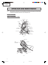
PRACTICAL APPLICATIONS
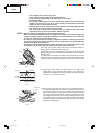
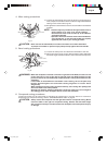
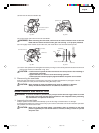
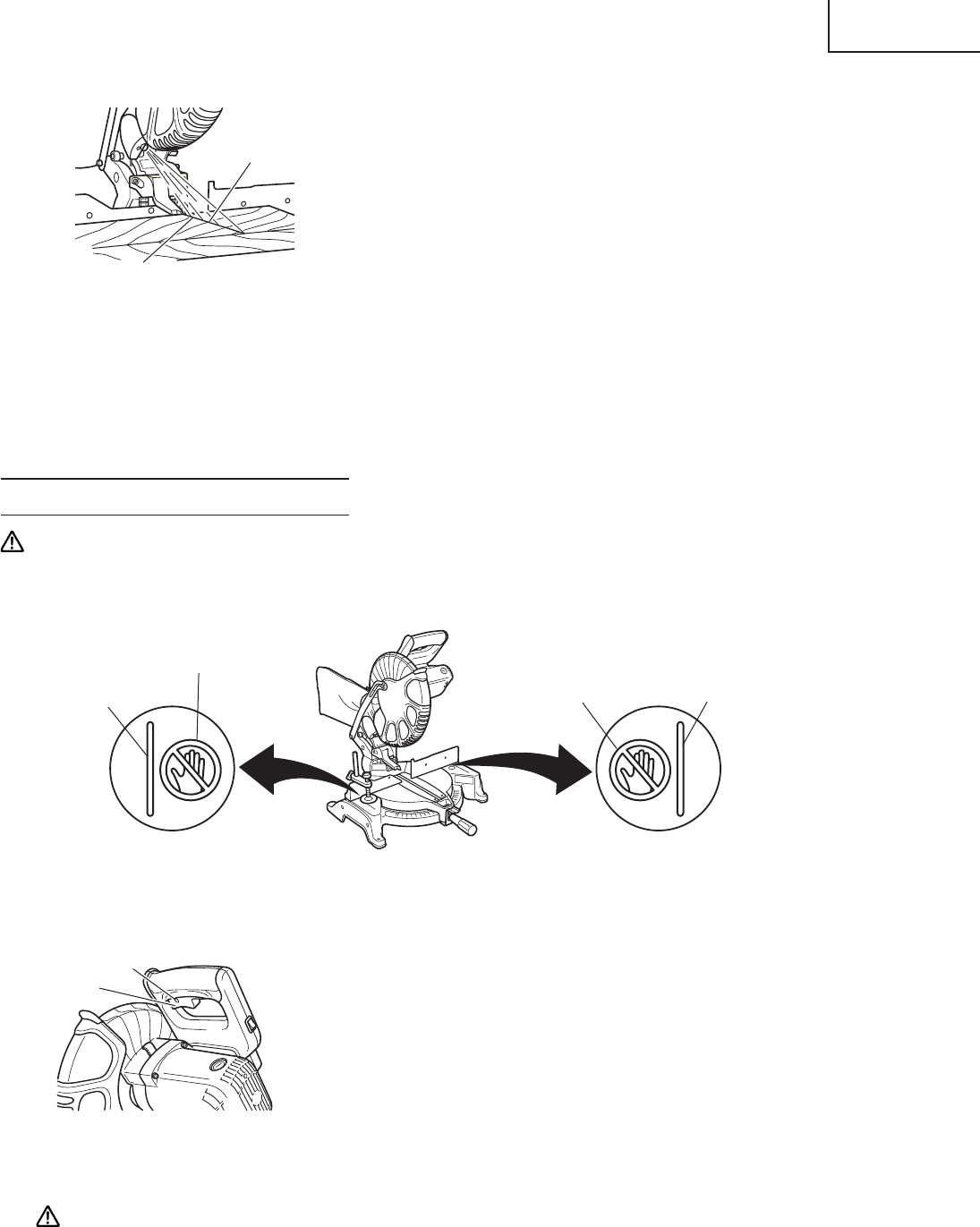
WARNING: * To avoid personal injury, never remove or place a workpiece on the table while the tool
is being operated.
* Never place your limbs inside of the line next to warning sign while the tool is being
operated. This may cause hazardous conditions (see Fig. 18).
Fig. 18
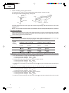
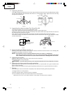
1. Switch operation
Pull the trigger to turn on the switch, release it to shut it off.
After releasing the trigger, make sure the trigger has gone all the
way back and the switch is turned off.
Fig. 19
WARNING: This will ensure that the power tool cannot be turned on accidentally or by someone
(especially a child) who is not qualified to use the power tool.
To prevent unauthorized operation of this tool, insert a padlock through the hole in
the switch trigger.
Laser Line
Marking
(pre-marked)
Trigger
Switch
Hole
Warning Sign
Line
Warning Sign
Line
01e_c10fch_e.p65 1/21/04, 0:05 PM15