


16
English
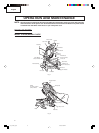
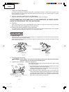
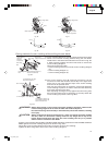
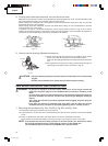
2. Using the Vise Assembly (Standard accessory)
(1) The vise assembly can be mounted on either the left fence
{Fence (B)} or the right fence {Fence (A)} by loosening the 6mm
wing bolt (A).
(2) The screw holder can be raised or lowered according to the
height of the workpiece by loosening the 6mm wing bolt (B).
After the adjustment, firmly tighten the 6mm wing bolt (B) and
fix the screw holder.
(3) Turn the upper knob and securely fix the workpiece in position
(Fig. 20).
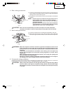
WARNING: Always firmly clamp or vise to secure the workpiece to the fence; otherwise the
workpiece might be thrust from the table and cause bodily harm.
CAUTION: Always confirm that the motor head (see Fig. 1) does not contact the vise assembly
when it is lowered for cutting. If there is any danger that it may do so, loosen the 6
mm wing bolt (B) and move the vise assembly to a position where it will not contact
the saw blade.
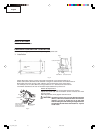
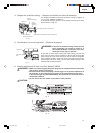
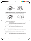
3. Cutting Operation
(1) As shown in Fig. 21 the width of the saw blade is the
width of the cut. Therefore, slide the workpiece to the
right (viewed from the operator’s position) when length
is desired, or to the left when length is desired.
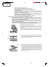
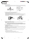
(Only Model C10FCH)
If a laser marker is used, align the laser line with the left
side of the saw blade, and then align the ink line with
the laser line.
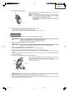
(2) Once the saw blade reaches maximum speed, push the
handle down carefully until the saw blade approaches
the workpiece.
(3) Once the saw blade contacts the workpiece, push the
handle down gradually to cut into the workpiece.
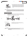
(4) After cutting the workpiece to the desired depth, turn
the power tool OFF and let the saw blade stop completely
before raising the handle from the workpiece to return
it to the full retract position.
WARNING: * Confirm that the trigger switch is turned OFF and the power plug has been removed
from the receptacle whenever the tool is not in use.
* When you cut the workpiece, avoid any cutoff thinner than the clearance between
the cutting edge and the saw blade. Otherwise, the cut-off material can enter the
clearance between the cutting edge and the saw blade and scatter around you,
resulting in an injury.
CAUTION: * Increased pressure on the handle will not increase the cutting speed.
On the contrary, too much pressure may result in overload of the motor and/or
decreased cutting efficiency.
* If the handle is pressed down with excessive or lateral force, the saw blade may
vibrate during the cutting operation and cause unwanted cutting marks on the
workpiece, thus reducing the quality of the cut. Accordingly, press the handle down
gently and carefully.
Fig. 20
Screw Holder
Knob
Workpiece
Vise Plate
6mm Wing
Bolt (B)
Fence
6mm Wing Bolt (A)
Fig. 21
Adjusting Line
Marking
(pre-marked)
Marking
(pre-marked)
(Front View)
Vise Shaft
01e_c10fch_e.p65 2/7/04, 16:0216