


English
19
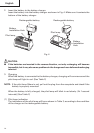
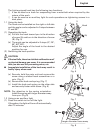
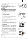
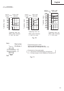
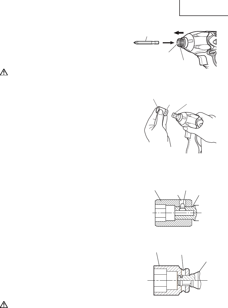
2. Installing the bit (WH12DM2, WH9DM2)
Always follow the following procedure to install
driver bit. (Fig. 13)
(1) Pull the guide sleeve back.
(2) Insert the bit into the hexagonal hole in the anvil.
(3) Release the guide sleeve and it returns to its
origianl position.
CAUTION:
● If the guide sleeve does not return to its original
position, then the bit is not installed properly.
3. Removing the bit (WH12DM2, WH9DM2)
Please do the opposite point on the method of
installing bit.
4. Selecting the socket matched to the bolt
(WR12DM2, WR9DM2)
Be sure to use a socket which is matched to the
bolt to be tightened. Using an improper socket will
not only result in insufficient tightening but also
in damage to the socket or nut.
A worn or deformed hex. or square-holed socket
will not give an adequate tightness for fitting to
the nut or anvil, consequently resulting in loss of
tightening torque.
Pay attention to wear of socket hole, and replace
before further wear has developed.
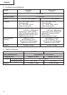
Matching socket and bolt sizes are shown Tables
4, 5, 6 and 7. The numerical value of a socket
designation denotes the side-to-side distance (H)
of its hex. hole.
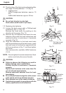
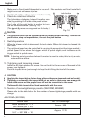
5. Installing a socket (Fig. 14, 15-1) (WR12DM2)
Align the plunger located in the square part of the
anvil with the hole in the hex. socket. Then push
the plunger, and mount the hex. socket on the
anvil. Check that the plunger is fully engaged in
the hole. When removing the socket, reverse the
sequence.
6. Retaining ring type (Fig. 14, 15-2) (WR9DM2)
(1) Align the square portions of the socket and the
anvil with each other.
(2) Make sure to firmly install the socket by pushing
it all the way into the anvil.
(3) When removing the socket, pull it out of the anvil.
CAUTION:
⅜ Please use the designated attachments which are listed in the operations manual and
Hitachi’s catalog. Accidents or injuries could result from not doing so.
Movement
Hexagonal
hole in the
anvil
Guide
sleeve
Driver bit
Fig. 14
Fig. 13
Hexagonal socket
Groove
Anvil
Plunger
Anvil
Hole
Fig. 15-1
Hexagonal
socket
Hexagonal
socket
Hole
Anvil
Fig. 15-2