


OM-951 Page 10
SECTION 4 − SPECIFICATIONS AND INSTALLATION
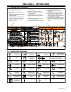
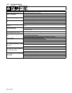
4-1. Specifications
Input Power
Single-Phase
AC
Rated Welding
Output
Welding
Amperage
Range
Max
OCV
DC
Amperes In-
put At Rated
Load Output,
50/60Hz,
Single-Phase
KVA @
Duty
Cycle
KW Dimensions Weight
115 Volts Stick
70A @ 22.8 Volts DC,
100% Duty Cycle
20 − 100A
90V
17.4 2.0 1.9
11
5
V
o
l
ts
S
t
i
c
k
100A @ 24.0 Volts DC,
35% Duty Cycle
20
−
100A
*12-16
26.4 3.0 3.0
115 Volts TIG
100A @ 14.0 Volts DC,
100% Duty Cycle
5 − 150A
90V
18.4 2.1 2.1
11
5
V
o
l
ts
TIG
150A @ 16.0 Volts DC,
30% Duty Cycle
5
−
1
5
0A
*12-16
28.0 3.4 3.1
H: 9 in (229 mm)
W: 5 5 in (140 mm)
13.7 lb
(6.2 kg)
230 Volts Stick
100A @ 24 Volts DC,
100% Duty Cycle
20 − 150A
90V
13.1 3.0 2.8
W: 5.5 in
(
140 mm
)
L: 13.25 in (337 mm)
(6
.
2 kg)
230 V
o
l
ts
S
t
i
c
k
150A @ 26.0 Volts DC,
30% Duty Cycle
20
−
1
5
0A
*12-16
21.6 4.9 4.7
230 Volts TIG
100A @ 14.0 Volts DC,
100% Duty Cycle
5 − 150A
90V
8.3 2.0 1.9
230 V
o
l
ts
TIG
150A @ 16.0 Volts DC,
30% Duty Cycle
5
−
1
5
0A
*12-16
14.2 3.2 3.1
*Sense Voltage For Stick And TIG Lift Arct
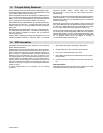
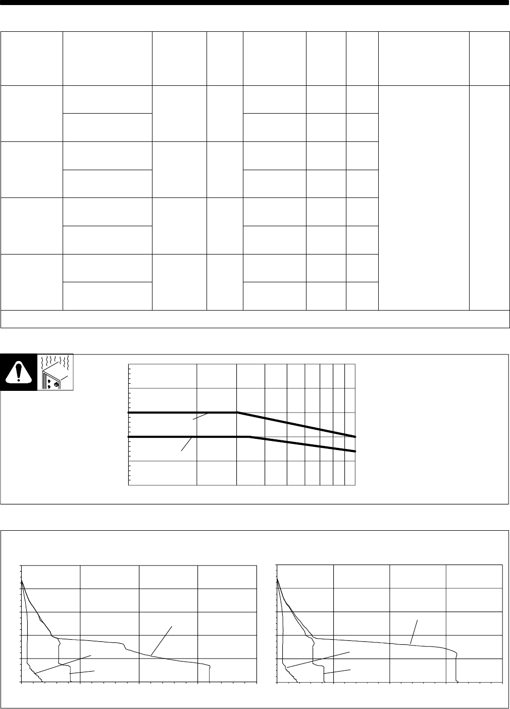
4-2. Duty Cycle And Overheating
208 608-C
Duty Cycle is percentage of 10 min-
utes that unit can weld at rated load
without overheating.
If unit overheats, output stops, the
Overtemperature Light comes On,
and the cooling fan runs. Wait fif-
teen minutes for unit to cool. Re-
duce amperage or duty cycle be-
fore starting to weld again.
Y Exceeding duty cycle can
damage unit and void
warranty.
% Duty Cycle
Output Amperes
10
100
0
50
100
150
200
250
Stick (230V)
Stick (115V)
TIG (115 &230V)
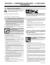
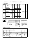
4-3. Volt-Ampere Curves
Volt-ampere curves show minimum and maximum voltage and amperage output capabilities
of welding power source. Curves of other settings fall between curves shown.
208 604-B
TIG/Stick Max
TIG Min
Stick Min
Amperes
Volts
115 VAC Input
230 VAC Input
Amperes
Volts
TIG/Stick Max
Stick Min
TIG Min
100
80
60
40
20
0
0 50 100 150 200
100
80
60
40
20
0
0 50 100 150 200