


OM-951 Page 12
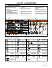
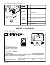
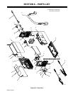
4-6. Remote 6 Receptacle Information
6
Socket Socket Information
15 VOLTS DC
1 Contactor control +13.8 volts DC.
15 VOLTS DC
OUTPUT
CONTACTOR
2 Contact closure to 1 completes contactor control
circuit and enables output when Lift-Arc TIG re-
mote is selected.
3 Output to remote control; +10 volts DC output to
remote control.
REMOTE
OUTPUT
CONTROL
4 0 to +10 volts DC input command signal from
remote control.
Ref. 803 351-D
5 Remote control circuit common.
CHASSIS
6 Chassis common.
SECTION 5 − OPERATION
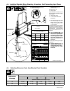
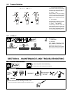
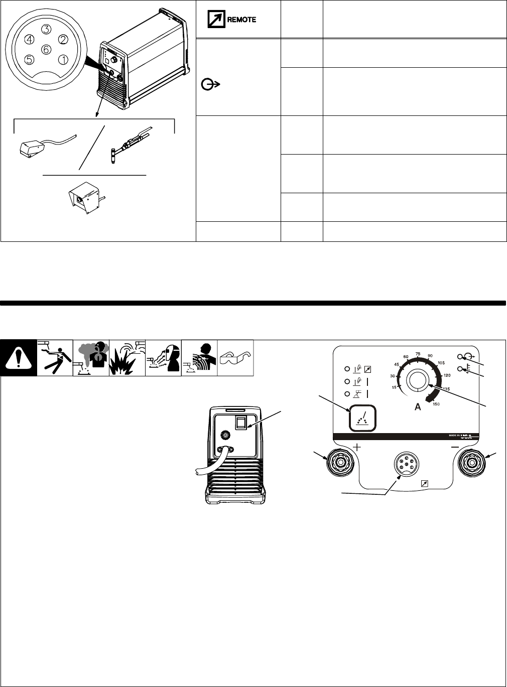
1 Ready Light
Light comes on approximately two seconds af-
ter power switch is placed in On (I) position if
Lift-Arc or Stick has been selected. The light in-
dicates that the unit is energized and ready for
welding. A flashing light indicates unit is not
ready, or that there is a functional error.
. The fan motor is thermostatically
controlled.
2 High Temperature Light
Light comes on if unit overheats. Once unit has
cooled down, welding can resume. If this light
flashes, take unit to an Authorized Service
Agent.
3 Amperage Adjustment Control
This control adjusts welding amperage.
4 Process Select Switch
See Section 5-2.
5 Positive Weld Output Receptacle
For Stick welding, connect electrode cable to
this receptacle. For TIG welding, connect work
cable to this receptacle.
6 Negative Weld Output Receptacle
For Stick welding, connect work cable to this
receptacle. For TIG welding, connect torch
cable to this receptacle.
7 Remote Receptacle
For Lift-Arc TIG, output may be adjusted from
min to max of the front panel setting with a re-
mote control. Also enables output in Lift-Arc re-
mote process (see Section 4-6).
8 Power Switch
Place switch in On (I) or Off (0) position as
needed.
5-1. Front Panel Controls
Ref. 803 375 / Ref. 218 320
7
5
6
4
8
3
2
1