


OM-951 Page 11
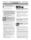
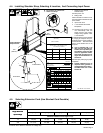
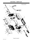
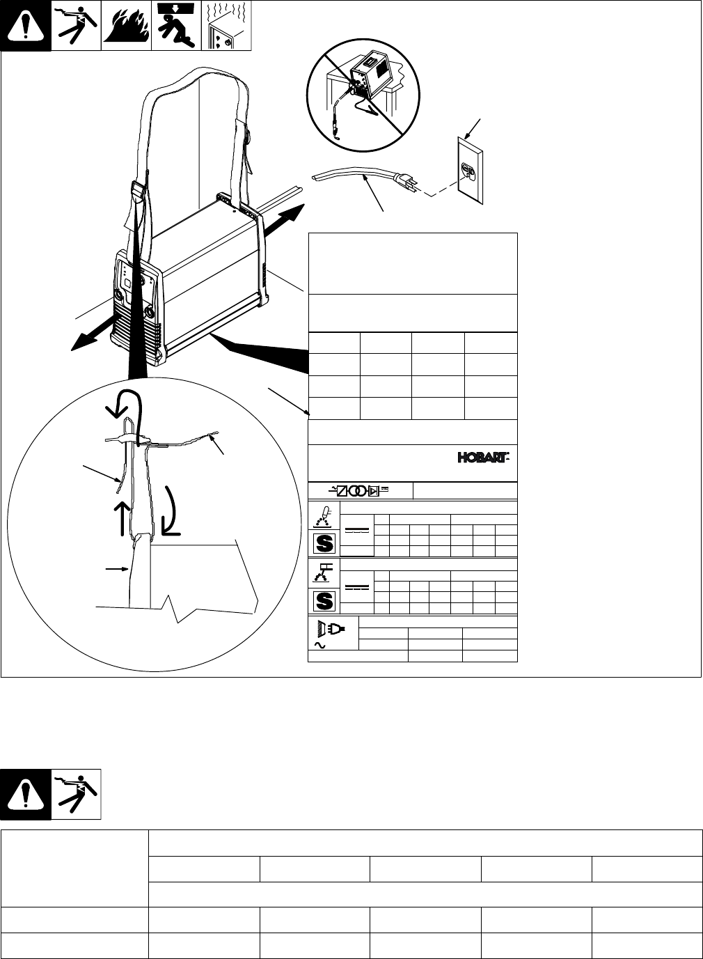
1 Welding Power Source
Shoulder Strap
Use strap to lift unit.
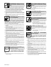
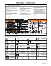
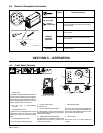
2 Rating Label
Label is located on bottom of unit.
Use rating label to determine input
power needs.
3 Input Power Cord
4 115 or 230 VAC Grounded
Receptacle
. The Auto-Line circuitry in this
unit automatically links the
power source to the primary
voltage being applied, either
115 or 230 VAC.
An individual branch circuit capable
of carrying 30 amperes and pro-
tected by fuses or circuit breaker is
recommended. Recommended
fuse or circuit breaker size is 30
amperes.
Y Unit is supplied with a 115
VAC plug. For 230 VAC op-
eration, have a qualified per-
son obtain a proper plug that
meets all applicable codes,
and install the plug accord-
ing to the manufacturer’s in-
structions.
Connect input power plug to proper
receptacle.
Y Special installation may be
required where gasoline or
volatile liquids are present −
see NEC Article 511 or CEC
Section 20.
Ref. 803 351-D / 218 322-A
3
4-4. Installing Shoulder Strap, Selecting A Location, And Connecting Input Power
18 in
(460 mm)
18 in
(460 mm)
Airflow Distance
Requirements
Y Do not move or operate unit
where it could tip.
2
1
Front Panel
To Rear Panel
4
EVIDENCE OF LABEL TAMPERING VOIDS WARRANTY
PROTECTED BY ONE OR MORE OF THE
FOLLOWING US. PATENTS:
(X,XXX,XXX)(X,XXX,XXX)(X,XXX,XXX)(X,XXX,XXX)
(X,XXX,XXX) (X,XXX,XXX) (X,XXX,XXX) (X,XXX,XXX)
(X,XXX,XXX)(X,XXX,XXX)(X,XXX,XXX)(X,XXX,XXX)
(X,XXX,XXX) (X,XXX,XXX) (X,XXX,XXX) (X,XXX,XXX)
(BAR CODE)
(SERIAL NUMBER)
XXXXXXXX
1
f2
30% 30%X
I
2
U
2
100%60%
150 150100120
16 161414.8
X
I
2
U
2
35% 30%100%60%
100 1507085
24 2622.823.4
1828
1323
Hz50/601
100%60%
120 100
14.8 14
100%60%
120 100
24.8 24
5A/20V 150A/26V
5A/10V 150A/16V
Hobart
Appleton, WI USA
Hobart 150 (XXX)
S/N: (XXXXXXXXXX)(XXXXXXXXXXXXX)
IP 23
For Help (XXXXXXXXXXXXXX)
U
1
=115V U
1
=230V
U
0
=90V
U
0
=90V
U
1
=115V
U
1
=230V
I
1
=max
I
1
=eff
U
1
=115V U
1
=230V
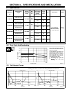
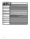
4-5. Selecting Extension Cord (Use Shortest Cord Possible)
Single Phase AC
Conductor Size − AWG [mm
2
]*
Single Phase AC
In
p
ut Volta
g
e
4 [21.2] 6 [13.3] 8 [8.4] 10 [5.3] 12 [3.3]
Input Voltage
Maximum Allowable Cord Length in ft (m)
115 160 (49) 107 (33) 71 (22) 47 (14) 29 (9)
230 471 (144) 321 (98) 215 (66) 146 (45) 90 (27)
*Conductor size is based on maximum 3% voltage drop