


OM-222 Page 17
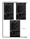
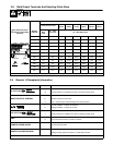
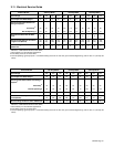
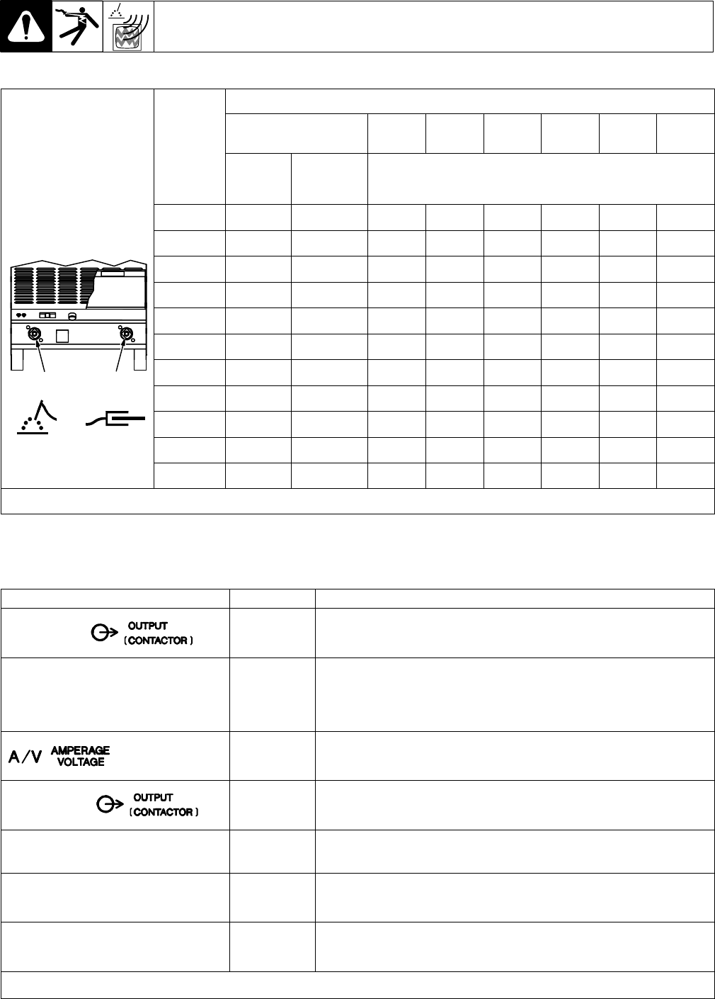
3-8. Weld Output Terminals And Selecting Cable Sizes
Total Cable (Copper) Length In Weld Circuit Not Exceeding
100 ft (30 m) Or Less
150 ft
(45 m)
200 ft
(60 m)
250 ft
(70 m)
300 ft
(90 m)
350 ft
(105 m)
400 ft
(120 m)
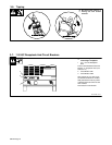
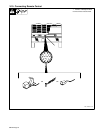
YTurn Off power before
connecting to weld output
terminals
Welding
Amperes
10 – 60%
Duty
Cycle
60 – 100%
Duty Cycle
10 – 100% Duty Cycle
100 4 4 4 3 2 1 1/0 1/0
150 3 3 2 1 1/0 2/0 3/0 3/0
200 3 2 1 1/0 2/0 3/0 4/0 4/0
250 2 1 1/0 2/0 3/0 4/0 2-2/0 2-2/0
300 1 1/0 2/0 3/0 4/0 2-2/0 2-3/0 2-3/0
350 1/0 2/0 3/0 4/0 2-2/0 2-3/0 2-3/0 2-4/0
400 1/0 2/0 3/0 4/0 2-2/0 2-3/0 2-4/0 2-4/0
Electrode Work
500 2/0 3/0 4/0 2-2/0 2-3/0 2-4/0 3-3/0 3-3/0
600 3/0 4/0 2-2/0 2-3/0 2-4/0 3-3/0 3-4/0 3-4/0
700 4/0 2-2/0 2-3/0 2-4/0 3-3/0 3-4/0 3-4/0 4-4/0
800 4/0 2-2/0 2-3/0 2-4/0 3-4/0 3-4/0 4-4/0 4-4/0
Weld cable size (AWG) is based on either a 4 volts or less drop or a current density of at least 300 circular mils per ampere. S-0007-D
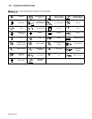
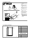
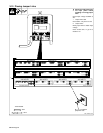
3-9. Remote 14 Receptacle Information
Socket Information
A 24 volts ac. Protected by circuit breaker CB2.
24 VOLTS AC
B Contact closure to A completes 24 volts ac contactor control circuit.
C Command reference; 0 to +10 volts dc.
REMOTE OUTPUT CONTROL
D Remote control circuit common.
E 0 to +10 volts dc input command signal from remote control.
F Current feedback; 1 volt per 100 amperes.
H Voltage feedback; 1 volt per 10 arc volts.
I 115 volts, 15 amperes, 60 Hz ac. Protected by circuit breaker CB1.
115 VOLTS AC
J Contact closure to I completes 115 volts ac contactor control circuit.
GND
K
G
Chassis common.
Circuit common for 24 and 115 volts ac circuits.
*
REMOTE POWER ON/OFF
*
To remote On/Off switch.
* Voltage sensing signal from Negative (-) weld output terminal.
REMOTE VOLTAGE SENSING
* Voltage sensing signal from Positive (+) weld output terminal.
* Not Used