


OM-222 Page 24
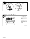
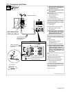
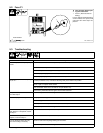
5-2. Fuse F1
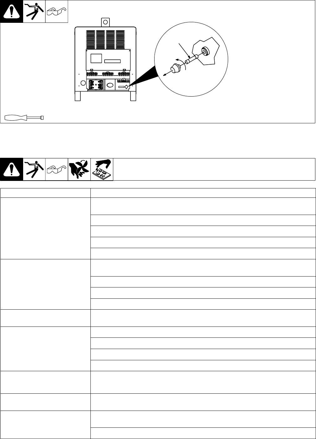
Ref. ST-800 101-C
Y Turn Off power before open-
ing rear access door.
1 Fuse F1 (See Parts List For
Rating)
Fuse F1 protects control transform-
er from overload. If F1 opens, weld
output and fan motor stops. Re-
place F1.
1
Tools Needed:
3/8 in
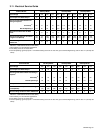
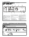
5-3. Troubleshooting
Trouble Remedy
No weld output; unit completely inop-
erative.
Place line disconnect switch in On position (see Section 3-13).
Check fuse F1, and replace if necessary (see Section 5-2).
Check and replace line fuse(s), if necessary, or reset circuit breaker (see Section 3-13).
Check for proper input power connections (see Section 3-13).
Check for proper jumper link position (see Section 3-12).
No weld output; Power switch pilot light
on; fan on.
If using remote control, place Output (Contactor) switch in Remote 14 position, and connect remote
control (see Section 3-10). If remote is not being used, place switch in On position.
Check, repair, or replace remote control.
Unit overheated. Allow unit to cool with fan On (see Section 3-2).
Have Factory Authorized Service Agent check control board PC1.
Unit provides only maximum or mini-
mum weld output.
Have Factory Authorized Service Agent check control board PC1 and hall device HD1.
Erratic or improper weld output. Use proper size and type of weld cable (see Section 3-8).
Clean and tighten all weld connections.
Check position of Polarity selector switch (see Section 4-1).
Have Factory Authorized Service Agent check control board PC1 and hall device HD1.
No 115 volts ac output at duplex recep-
tacle, Remote 14 receptacle, or termi-
nal strip 1T.
Reset circuit breaker CB1 (see Section 3-7).
No 24 volts ac output at Remote 14 re-
ceptacle, or terminal strip 1T.
Reset circuit breaker CB2 (see Section 3-7).
Fan not operating. NOTE: fan only
runs when cooling is necessary.
Check for and remove anything blocking fan movement.
Have Factory Authorized Service Agent check fan motor.